
User's Manual
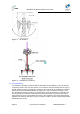
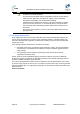
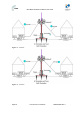
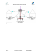
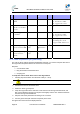
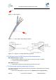
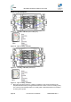
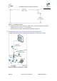
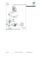
Table Of Contents
- 1.1 Purpose
- 1.4 Referenced Documentation
- 2.1 MicroMAX Frequency Ranges
- 2.2 System Components
- 2.3 Customer Benefits
- 2.4 Architecture
- 2.5 Power
- 2.6 Models
- 3.1 Package Contents
- 3.2 Required Tools
- 3.3 Radio Site Planning
- 4.1 MicroMAX BSR
- 4.2 SDA-4S Type II
- 4.3 SDA-4SDC Type II
- 5.1 Physical Dimensions
- 5.2 Ports
- 6.1 Physical Dimensions
- 6.2 Ports
- 6.3 LEDs
- 6.4 Mounting the GPSD
- 6.5 GPSD Architecture
- 7.1 Physical Dimensions
- 7.2 Ports
- 7.3 Crimping GPS Cable
- 7.4 Contact Socket Crimping
- 8.2 Redundant PS Unit
- 9.1 Pole-Mounting the BSR
- 9.2 Wall-Mounting the BSR (Optional)
- 9.3 Installing the SDA-4S
- 10.1 Desktop mounting
- 10.2 Rack mounting
- 12.1 Rack Mounting
- 12.2 Connecting Redundant PS Unit
- 13.1 Connecting the BSR to the SDA-4S
- 13.2 SDA-4S Type II
- 13.3 Connecting the BSR to BSDU
- 13.4 Connecting BSDU to Network
- 13.5 Connecting BSDUs
- 13.6 Connecting BSDU for SNMP Management
- 14.1 Connecting the SDA-4S Type II
- 14.2 Connecting the SDA-4SDC Type II
- 14.3 Connecting SDA-4S to Ethernet Network
- 15.1 Housing the Connectors
- 15.2 Connecting to the SDA-4SDC
- 16.1 Connections
- 16.2 Power Cable Assembly
- 16.3 Housing the Connectors
- 16.4 Cable Connection
- 17.1 Lightning Protection
- 17.2 Cable Preparation (for grounding)
- 17.3 FM Interference & ESD Protection Recommendations
- 17.4 Connecting Lightning and Surge Protector
- 17.5 Lightning and Surge Protection Connection Scenarios
- 18.1 Connecting GPS Antenna to BSDU
- 19.1 Environmental
- 19.2 Glossary of Terms
- 19.3 Revision History
- 19.4 Contact Information

MicroMAX Hardware Installation User Guide
Page 85 Commercial in Confidence UWB-D00068 Rev J
Table 30 – Accessories
Item
No.
Description Manufacturer Manufacturer
P/N
QuantityRemark
1
Copper wire 0
AWG
N/A
N/A N/A Ground resistance must
be less than 1 Ohm.
UL approved cable
2
CAT-5e SFTP with
drain and double
jacket
N/A
N/A N/A Up to 100 meters
3
Bare Copper Wire
4/0 AWG
N/A
N/A N/A Ground resistance must
be less than 5 Ohm.
UL approved cable
Ring terminal
N/A
N/A N/A Stud H (1/4), Diameter
matching the used
Copper Wire diameter.
Circuit Lightning
protection for BSR
Polyphaser IX
series
IX-
2H1L1DC48-
IG
1
Installed with BSR
Circuit Lightning
protection for
ProST
Polyphaser IX
series
IX-2H1DC48-
IG
1
Installed with ProST
17.2 Cable Preparation (for grounding)
The CAT-5e SFTP cable is supplied unassembled. Therefore, you need to crimp the drain wire to
the ring terminal and paired wires to the connector's contact pins.
Required:
¾ CAT-5e SFTP cable
¾ Ring terminal and red insulation boot
¾ Crimping tool
To crimp the CAT-5e SFTP “drain” wire to the ring terminal:
1. Carefully strip the insulation from the SFTP cable (5 – 10cm).
Caution: Do not damage the insulation of the inner twisted pair wires.
2. Peel back the foil from around the wires.
3. Isolate the “drain” (ground) wire.
4. Crimp the ring terminal to the drain wire. Insert the wire into the ring terminal’s barrel, and
then, with a standard crimping tool crimp the barrel tightly onto the wire. Fold back the drain
wire with the ring terminal attached.
5. Strip the ends of the paired wires according to the connector.
6. Connect ground wire (with extension if required) to the tower.
The figures and connections are displayed below: