
User's Manual
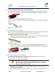
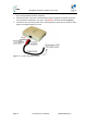
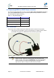
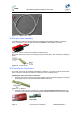
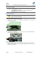
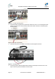
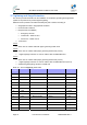
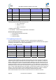
Table Of Contents
- 1.1 Purpose
- 1.4 Referenced Documentation
- 2.1 MicroMAX Frequency Ranges
- 2.2 System Components
- 2.3 Customer Benefits
- 2.4 Architecture
- 2.5 Power
- 2.6 Models
- 3.1 Package Contents
- 3.2 Required Tools
- 3.3 Radio Site Planning
- 4.1 MicroMAX BSR
- 4.2 SDA-4S Type II
- 4.3 SDA-4SDC Type II
- 5.1 Physical Dimensions
- 5.2 Ports
- 6.1 Physical Dimensions
- 6.2 Ports
- 6.3 LEDs
- 6.4 Mounting the GPSD
- 6.5 GPSD Architecture
- 7.1 Physical Dimensions
- 7.2 Ports
- 7.3 Crimping GPS Cable
- 7.4 Contact Socket Crimping
- 8.2 Redundant PS Unit
- 9.1 Pole-Mounting the BSR
- 9.2 Wall-Mounting the BSR (Optional)
- 9.3 Installing the SDA-4S
- 10.1 Desktop mounting
- 10.2 Rack mounting
- 12.1 Rack Mounting
- 12.2 Connecting Redundant PS Unit
- 13.1 Connecting the BSR to the SDA-4S
- 13.2 SDA-4S Type II
- 13.3 Connecting the BSR to BSDU
- 13.4 Connecting BSDU to Network
- 13.5 Connecting BSDUs
- 13.6 Connecting BSDU for SNMP Management
- 14.1 Connecting the SDA-4S Type II
- 14.2 Connecting the SDA-4SDC Type II
- 14.3 Connecting SDA-4S to Ethernet Network
- 15.1 Housing the Connectors
- 15.2 Connecting to the SDA-4SDC
- 16.1 Connections
- 16.2 Power Cable Assembly
- 16.3 Housing the Connectors
- 16.4 Cable Connection
- 17.1 Lightning Protection
- 17.2 Cable Preparation (for grounding)
- 17.3 FM Interference & ESD Protection Recommendations
- 17.4 Connecting Lightning and Surge Protector
- 17.5 Lightning and Surge Protection Connection Scenarios
- 18.1 Connecting GPS Antenna to BSDU
- 19.1 Environmental
- 19.2 Glossary of Terms
- 19.3 Revision History
- 19.4 Contact Information

MicroMAX Hardware Installation User Guide
Page 75 Commercial in Confidence UWB-D00068 Rev J
This cable connects between the rear panel of the AC/DC Converter and the -48V Power Input on
the Front Panel of the BSDU.
Note: Ensure that:
The POSITIVE output of the AC/DC Converter is connected to the POSITIVE
(Red) input (lower) on the BSDU.
The NEGATIVE output of the AC/DC Converter is connected to the
NEGATIVE (Black) input (upper) on the BSDU.
16.4 Cable Connection
Caution: Confirm that all inputs to the AC/DC converter are either
disconnected or powered off prior to installing the cable, otherwise damage
may occur to either or both devices.
To connect the BSDU to AC/DC Converter Cable
1. Connect the end of cable 63000110 labeled BSDU to the PS MNG port on the back panel of
the BSDU, as shown below.
Figure 63 - BSDU to PS MNG port
2. Connect the end of cable 63000110 marked ‘PSU’ to the ‘J1’ port on the back panel of the
AC/DC Convertor, as shown below.
Figure 64 - PSU to J1 port
3. Connect the Black crimped wire from the 25-pin cable connected to Port J1 on the back
panel of the AC/DC Convertor to the –VDC (Negative) output of the AC/DC Convertor on the
back panel, as shown below.