
User's Manual
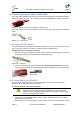
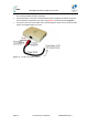
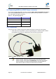
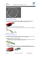
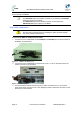
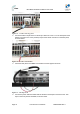
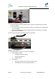
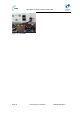
Table Of Contents
- 1.1 Purpose
- 1.4 Referenced Documentation
- 2.1 MicroMAX Frequency Ranges
- 2.2 System Components
- 2.3 Customer Benefits
- 2.4 Architecture
- 2.5 Power
- 2.6 Models
- 3.1 Package Contents
- 3.2 Required Tools
- 3.3 Radio Site Planning
- 4.1 MicroMAX BSR
- 4.2 SDA-4S Type II
- 4.3 SDA-4SDC Type II
- 5.1 Physical Dimensions
- 5.2 Ports
- 6.1 Physical Dimensions
- 6.2 Ports
- 6.3 LEDs
- 6.4 Mounting the GPSD
- 6.5 GPSD Architecture
- 7.1 Physical Dimensions
- 7.2 Ports
- 7.3 Crimping GPS Cable
- 7.4 Contact Socket Crimping
- 8.2 Redundant PS Unit
- 9.1 Pole-Mounting the BSR
- 9.2 Wall-Mounting the BSR (Optional)
- 9.3 Installing the SDA-4S
- 10.1 Desktop mounting
- 10.2 Rack mounting
- 12.1 Rack Mounting
- 12.2 Connecting Redundant PS Unit
- 13.1 Connecting the BSR to the SDA-4S
- 13.2 SDA-4S Type II
- 13.3 Connecting the BSR to BSDU
- 13.4 Connecting BSDU to Network
- 13.5 Connecting BSDUs
- 13.6 Connecting BSDU for SNMP Management
- 14.1 Connecting the SDA-4S Type II
- 14.2 Connecting the SDA-4SDC Type II
- 14.3 Connecting SDA-4S to Ethernet Network
- 15.1 Housing the Connectors
- 15.2 Connecting to the SDA-4SDC
- 16.1 Connections
- 16.2 Power Cable Assembly
- 16.3 Housing the Connectors
- 16.4 Cable Connection
- 17.1 Lightning Protection
- 17.2 Cable Preparation (for grounding)
- 17.3 FM Interference & ESD Protection Recommendations
- 17.4 Connecting Lightning and Surge Protector
- 17.5 Lightning and Surge Protection Connection Scenarios
- 18.1 Connecting GPS Antenna to BSDU
- 19.1 Environmental
- 19.2 Glossary of Terms
- 19.3 Revision History
- 19.4 Contact Information

MicroMAX Hardware Installation User Guide
Page 74 Commercial in Confidence UWB-D00068 Rev J
¾ BSDU to DC power supply cable (supplied with the BSDU)
Figure 58 - BSDU to DC cable
16.2 Power Cable Assembly
In the BSDU Kit there are two polarized and genderless unassembled Anderson Powerpole
power connectors: red for positive connection and black for the negative connection.
Figure 59 - Power connectors (Anderson Powerpole)
The power connectors consist of housing (hood and a contact pins). The contact pin is displayed
below:
Figure 60 - Contact pin
16.3 Housing the Connectors
The power connectors are supplied unassembled. Therefore, you need to crimp the power wires
to the connector's contact pins, and then house them in the Powerpole hood.
Crimping the power wires to the connectors:
1. Insert the wire into the contact pin's barrel, and then, with a standard crimping tool crimp the
barrel tightly onto the wire (recommended 20AWG cable wire).
Figure 61 – Crimped
2. Insert the contact into the hood with the contact's tongue pointing downwards and snap
into place. Ensure that the housing spring mates with the underside of the contact's tongue.
Figure 62 - Insertion