
User's Manual
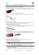
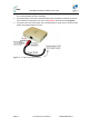
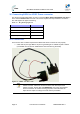
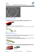
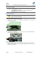
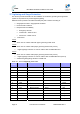
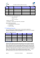
Table Of Contents
- 1.1 Purpose
- 1.4 Referenced Documentation
- 2.1 MicroMAX Frequency Ranges
- 2.2 System Components
- 2.3 Customer Benefits
- 2.4 Architecture
- 2.5 Power
- 2.6 Models
- 3.1 Package Contents
- 3.2 Required Tools
- 3.3 Radio Site Planning
- 4.1 MicroMAX BSR
- 4.2 SDA-4S Type II
- 4.3 SDA-4SDC Type II
- 5.1 Physical Dimensions
- 5.2 Ports
- 6.1 Physical Dimensions
- 6.2 Ports
- 6.3 LEDs
- 6.4 Mounting the GPSD
- 6.5 GPSD Architecture
- 7.1 Physical Dimensions
- 7.2 Ports
- 7.3 Crimping GPS Cable
- 7.4 Contact Socket Crimping
- 8.2 Redundant PS Unit
- 9.1 Pole-Mounting the BSR
- 9.2 Wall-Mounting the BSR (Optional)
- 9.3 Installing the SDA-4S
- 10.1 Desktop mounting
- 10.2 Rack mounting
- 12.1 Rack Mounting
- 12.2 Connecting Redundant PS Unit
- 13.1 Connecting the BSR to the SDA-4S
- 13.2 SDA-4S Type II
- 13.3 Connecting the BSR to BSDU
- 13.4 Connecting BSDU to Network
- 13.5 Connecting BSDUs
- 13.6 Connecting BSDU for SNMP Management
- 14.1 Connecting the SDA-4S Type II
- 14.2 Connecting the SDA-4SDC Type II
- 14.3 Connecting SDA-4S to Ethernet Network
- 15.1 Housing the Connectors
- 15.2 Connecting to the SDA-4SDC
- 16.1 Connections
- 16.2 Power Cable Assembly
- 16.3 Housing the Connectors
- 16.4 Cable Connection
- 17.1 Lightning Protection
- 17.2 Cable Preparation (for grounding)
- 17.3 FM Interference & ESD Protection Recommendations
- 17.4 Connecting Lightning and Surge Protector
- 17.5 Lightning and Surge Protection Connection Scenarios
- 18.1 Connecting GPS Antenna to BSDU
- 19.1 Environmental
- 19.2 Glossary of Terms
- 19.3 Revision History
- 19.4 Contact Information

MicroMAX Hardware Installation User Guide
Page 73 Commercial in Confidence UWB-D00068 Rev J
16 Connecting BSDU to AC/DC Power converter
This section provides a description of how to connect the Base Station Distribution Unit (BSDU)
to the external AC/DC Power converter. This section explains the steps needed to connect the
two units together for proper functioning.
Table 27 - Required Equipment
Equipment Description Part number
BSDU MMX-BSDU-1
AC/DC Converter PC-BSDU-1
BSDU to AC/DC Converter Cable 68000110
BSDU to DC power Supply Cable supplied with BSDU kit
16.1 Connections
There are two sets of cables required for the BSDU and AC/DC converter to work properly.
¾ Cable with 25-pin D-type Male to 25-pin D-Type Male (part no. 68000110) with 2 cables
(UL 20AWG red color and UL 20AWG black color both with ring terminals).
Figure 57 - BSDU - AC/DC cable
Note: This cable connects between the rear panels of the BSDU and the
AC/DC converter. It also has connections to the main DC Output of the
AC/DC converter, but the cable itself DOES NOT carry power to the BSDU.
These connections are used for sensing purposes, so that the PSU can
adjust the DC output according to the load drawn by the BSDU.