
User's Manual
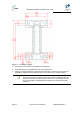
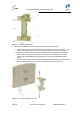
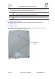
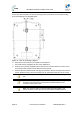
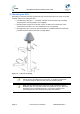
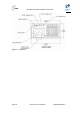
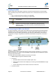
Table Of Contents
- 1.1 Purpose
- 1.4 Referenced Documentation
- 2.1 MicroMAX Frequency Ranges
- 2.2 System Components
- 2.3 Customer Benefits
- 2.4 Architecture
- 2.5 Power
- 2.6 Models
- 3.1 Package Contents
- 3.2 Required Tools
- 3.3 Radio Site Planning
- 4.1 MicroMAX BSR
- 4.2 SDA-4S Type II
- 4.3 SDA-4SDC Type II
- 5.1 Physical Dimensions
- 5.2 Ports
- 6.1 Physical Dimensions
- 6.2 Ports
- 6.3 LEDs
- 6.4 Mounting the GPSD
- 6.5 GPSD Architecture
- 7.1 Physical Dimensions
- 7.2 Ports
- 7.3 Crimping GPS Cable
- 7.4 Contact Socket Crimping
- 8.2 Redundant PS Unit
- 9.1 Pole-Mounting the BSR
- 9.2 Wall-Mounting the BSR (Optional)
- 9.3 Installing the SDA-4S
- 10.1 Desktop mounting
- 10.2 Rack mounting
- 12.1 Rack Mounting
- 12.2 Connecting Redundant PS Unit
- 13.1 Connecting the BSR to the SDA-4S
- 13.2 SDA-4S Type II
- 13.3 Connecting the BSR to BSDU
- 13.4 Connecting BSDU to Network
- 13.5 Connecting BSDUs
- 13.6 Connecting BSDU for SNMP Management
- 14.1 Connecting the SDA-4S Type II
- 14.2 Connecting the SDA-4SDC Type II
- 14.3 Connecting SDA-4S to Ethernet Network
- 15.1 Housing the Connectors
- 15.2 Connecting to the SDA-4SDC
- 16.1 Connections
- 16.2 Power Cable Assembly
- 16.3 Housing the Connectors
- 16.4 Cable Connection
- 17.1 Lightning Protection
- 17.2 Cable Preparation (for grounding)
- 17.3 FM Interference & ESD Protection Recommendations
- 17.4 Connecting Lightning and Surge Protector
- 17.5 Lightning and Surge Protection Connection Scenarios
- 18.1 Connecting GPS Antenna to BSDU
- 19.1 Environmental
- 19.2 Glossary of Terms
- 19.3 Revision History
- 19.4 Contact Information

MicroMAX Hardware Installation User Guide
Page 58 Commercial in Confidence UWB-D00068 Rev J
12 Mounting the AC/DC Power Converter
The AC/DC Power Converter is to be mounted horizontally in a rack (ETSI or 19“)
12.1 Rack Mounting
The AC/DC Power Converter is designed for mounting in a standard 19-inch (48.3 cm) ETSI
equipment rack or telco rack with 1-rack unit (1-U) of vertical rack space. Mounting bracket
flanges are provided for mounting the AC/DC Power Converter into the cabinet, in its kit.
Therefore, all that is required for mounting the AC/DC Power Converter is to attach the AC/DC
Power Converter front-rail mounting brackets to the rack's mounting rails using the four M5-
mounting screws and plastic cup washers.
To rack-mount the AC/DC Power Converter:
1. Determine the rack rail holes (left and right side) that will be used for attaching the chassis.
2. Insert four nuts into the rack's rail holes you designated in Step 1. These nuts are housed in
Tinnerman clips, which allow you to fasten them into the rail holes. To insert the Tinnerman
clips, hold the clips, squeeze them, and then insert them into the rail hole.
3. Carefully insert the AC/DC Power Converter into the rack, aligning the AC/DC Power
Converter's mounting bracket holes with the rack rail holes.
4. Insert the M5-mounting screws, with plastic washers, into the AC/DC Power Converter
mounting bracket holes, on each side, as shown in figure below. In this way, the chassis is
supported until you tighten the chassis screws.
5. Tighten the M5-mounting screws to fasten the chassis to the cabinet.
12.2 Connecting Redundant PS Unit
When required an additional PS unit is available (optional) for redundancy. This hot-swappable
unit is designed for ease of installation.
To install an additional PS unit
1. Check that the recessed on/off switch is in the off position
2. Determine the location to mount the redundant PS unit in the AC/DC Power Converter's
chassis housing (usually to the left on the presently installed unit).
3. Carefully slide the unit on the rail tray until flush with front of AC/DC Power Converter's
chassis housing.
4. Secure the unit by turning the Latch Lock screw, using a flat screw driver
5. Set the DIP switches (located on the back of the PS unit) to the on position for all 5 switches.