
User's Manual
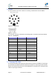
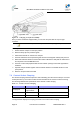
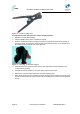
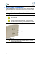
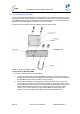
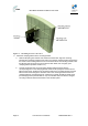
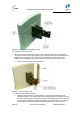
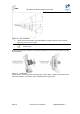
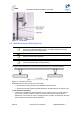
Table Of Contents
- 1.1 Purpose
- 1.4 Referenced Documentation
- 2.1 MicroMAX Frequency Ranges
- 2.2 System Components
- 2.3 Customer Benefits
- 2.4 Architecture
- 2.5 Power
- 2.6 Models
- 3.1 Package Contents
- 3.2 Required Tools
- 3.3 Radio Site Planning
- 4.1 MicroMAX BSR
- 4.2 SDA-4S Type II
- 4.3 SDA-4SDC Type II
- 5.1 Physical Dimensions
- 5.2 Ports
- 6.1 Physical Dimensions
- 6.2 Ports
- 6.3 LEDs
- 6.4 Mounting the GPSD
- 6.5 GPSD Architecture
- 7.1 Physical Dimensions
- 7.2 Ports
- 7.3 Crimping GPS Cable
- 7.4 Contact Socket Crimping
- 8.2 Redundant PS Unit
- 9.1 Pole-Mounting the BSR
- 9.2 Wall-Mounting the BSR (Optional)
- 9.3 Installing the SDA-4S
- 10.1 Desktop mounting
- 10.2 Rack mounting
- 12.1 Rack Mounting
- 12.2 Connecting Redundant PS Unit
- 13.1 Connecting the BSR to the SDA-4S
- 13.2 SDA-4S Type II
- 13.3 Connecting the BSR to BSDU
- 13.4 Connecting BSDU to Network
- 13.5 Connecting BSDUs
- 13.6 Connecting BSDU for SNMP Management
- 14.1 Connecting the SDA-4S Type II
- 14.2 Connecting the SDA-4SDC Type II
- 14.3 Connecting SDA-4S to Ethernet Network
- 15.1 Housing the Connectors
- 15.2 Connecting to the SDA-4SDC
- 16.1 Connections
- 16.2 Power Cable Assembly
- 16.3 Housing the Connectors
- 16.4 Cable Connection
- 17.1 Lightning Protection
- 17.2 Cable Preparation (for grounding)
- 17.3 FM Interference & ESD Protection Recommendations
- 17.4 Connecting Lightning and Surge Protector
- 17.5 Lightning and Surge Protection Connection Scenarios
- 18.1 Connecting GPS Antenna to BSDU
- 19.1 Environmental
- 19.2 Glossary of Terms
- 19.3 Revision History
- 19.4 Contact Information

MicroMAX Hardware Installation User Guide
Page 48 Commercial in Confidence UWB-D00068 Rev J
Figure 28 - Pole mount clamping bracket
10. Attach the U-bolt to the pole:
3. Place one U-bolt around the pole, and then insert the U-bolt screw side through the two
corresponding holes (horizontally parallel) on the clamping bracket. Slide an M8-flat washer
and M8-spring lock washer onto each U-bolt screw side (ensure that the flat washer is
adjacent to the clamping bracket). Fasten each U-bolt side with the two M8-hex nuts.
d. Attach the second U-bolt as described above.
Figure 29 - Pole mount U-bolts
11. Perform final MicroMAX orientation:
a. Adjust the vertical position of the MicroMAX by choosing a final elevation hole as
described in Step 2. Lock the MicroMAX at the desired position by inserting the locking
bolt in the desired position and fastening it tightly. Fasten tightly the bolt in the pivot hole.
The figure below illustrates the angles (in degrees) of each elevation hole. As shown,
the MicroMAX pole-mounting bracket allows elevation between -18.5° and 26.3°.