
User's Manual
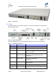
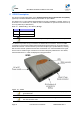
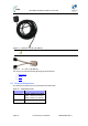
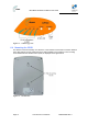
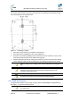
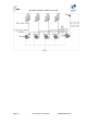
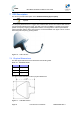
Table Of Contents
- 1.1 Purpose
- 1.4 Referenced Documentation
- 2.1 MicroMAX Frequency Ranges
- 2.2 System Components
- 2.3 Customer Benefits
- 2.4 Architecture
- 2.5 Power
- 2.6 Models
- 3.1 Package Contents
- 3.2 Required Tools
- 3.3 Radio Site Planning
- 4.1 MicroMAX BSR
- 4.2 SDA-4S Type II
- 4.3 SDA-4SDC Type II
- 5.1 Physical Dimensions
- 5.2 Ports
- 6.1 Physical Dimensions
- 6.2 Ports
- 6.3 LEDs
- 6.4 Mounting the GPSD
- 6.5 GPSD Architecture
- 7.1 Physical Dimensions
- 7.2 Ports
- 7.3 Crimping GPS Cable
- 7.4 Contact Socket Crimping
- 8.2 Redundant PS Unit
- 9.1 Pole-Mounting the BSR
- 9.2 Wall-Mounting the BSR (Optional)
- 9.3 Installing the SDA-4S
- 10.1 Desktop mounting
- 10.2 Rack mounting
- 12.1 Rack Mounting
- 12.2 Connecting Redundant PS Unit
- 13.1 Connecting the BSR to the SDA-4S
- 13.2 SDA-4S Type II
- 13.3 Connecting the BSR to BSDU
- 13.4 Connecting BSDU to Network
- 13.5 Connecting BSDUs
- 13.6 Connecting BSDU for SNMP Management
- 14.1 Connecting the SDA-4S Type II
- 14.2 Connecting the SDA-4SDC Type II
- 14.3 Connecting SDA-4S to Ethernet Network
- 15.1 Housing the Connectors
- 15.2 Connecting to the SDA-4SDC
- 16.1 Connections
- 16.2 Power Cable Assembly
- 16.3 Housing the Connectors
- 16.4 Cable Connection
- 17.1 Lightning Protection
- 17.2 Cable Preparation (for grounding)
- 17.3 FM Interference & ESD Protection Recommendations
- 17.4 Connecting Lightning and Surge Protector
- 17.5 Lightning and Surge Protection Connection Scenarios
- 18.1 Connecting GPS Antenna to BSDU
- 19.1 Environmental
- 19.2 Glossary of Terms
- 19.3 Revision History
- 19.4 Contact Information

MicroMAX Hardware Installation User Guide
Page 38 Commercial in Confidence UWB-D00068 Rev J
To wall mount the GPSD:
On the wall, mark the position of the two mounting hooks. The dimensions of the wall-mounting
hooks are displayed in the template below.
Figure 15 - mounting template
1. Drill holes for each hole that you marked in the step above.
2. Insert wall anchors (supplied) into each of the drilled holes.
3. Insert the 9-inch screws (supplied) into the wall anchors. Ensure at least 2 mm of the screw
is exposed to allow insertion into the GPSD mounting holes.
4. Hold the GPSD with both hands, and align the entrance to the two mounting hooks with the
screws. Slide the screws into the mounting hooks, by lowering the GPSD onto the screws.
Note: For safety, both mounting hooks must be utilized when mounting the
unit.
Note: The GPSD is supplied with a 1-metre AC power lead assembly.
Therefore, ensure the unit is mounted within reachable distance to the
customer's mains power outlet.
Note: The maximum cable run between GPSD and MicroMAX is 100 meters.
Therefore, ensure the unit is mounted within reachable distance.
6.5 GPSD Architecture
The figures below display a typical setup, using the GPSD, multiple BSR(s), multiple SDA-4S or
SDA-4SDC, “y” cable and the GPS antenna.
Note: Alternately you can use the supplied external antenna which is limited
to 5 meters long.