
User's Manual
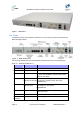
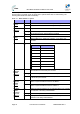
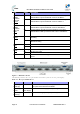
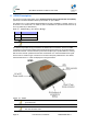
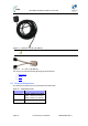
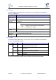
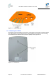
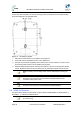
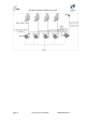
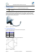
Table Of Contents
- 1.1 Purpose
- 1.4 Referenced Documentation
- 2.1 MicroMAX Frequency Ranges
- 2.2 System Components
- 2.3 Customer Benefits
- 2.4 Architecture
- 2.5 Power
- 2.6 Models
- 3.1 Package Contents
- 3.2 Required Tools
- 3.3 Radio Site Planning
- 4.1 MicroMAX BSR
- 4.2 SDA-4S Type II
- 4.3 SDA-4SDC Type II
- 5.1 Physical Dimensions
- 5.2 Ports
- 6.1 Physical Dimensions
- 6.2 Ports
- 6.3 LEDs
- 6.4 Mounting the GPSD
- 6.5 GPSD Architecture
- 7.1 Physical Dimensions
- 7.2 Ports
- 7.3 Crimping GPS Cable
- 7.4 Contact Socket Crimping
- 8.2 Redundant PS Unit
- 9.1 Pole-Mounting the BSR
- 9.2 Wall-Mounting the BSR (Optional)
- 9.3 Installing the SDA-4S
- 10.1 Desktop mounting
- 10.2 Rack mounting
- 12.1 Rack Mounting
- 12.2 Connecting Redundant PS Unit
- 13.1 Connecting the BSR to the SDA-4S
- 13.2 SDA-4S Type II
- 13.3 Connecting the BSR to BSDU
- 13.4 Connecting BSDU to Network
- 13.5 Connecting BSDUs
- 13.6 Connecting BSDU for SNMP Management
- 14.1 Connecting the SDA-4S Type II
- 14.2 Connecting the SDA-4SDC Type II
- 14.3 Connecting SDA-4S to Ethernet Network
- 15.1 Housing the Connectors
- 15.2 Connecting to the SDA-4SDC
- 16.1 Connections
- 16.2 Power Cable Assembly
- 16.3 Housing the Connectors
- 16.4 Cable Connection
- 17.1 Lightning Protection
- 17.2 Cable Preparation (for grounding)
- 17.3 FM Interference & ESD Protection Recommendations
- 17.4 Connecting Lightning and Surge Protector
- 17.5 Lightning and Surge Protection Connection Scenarios
- 18.1 Connecting GPS Antenna to BSDU
- 19.1 Environmental
- 19.2 Glossary of Terms
- 19.3 Revision History
- 19.4 Contact Information

MicroMAX Hardware Installation User Guide
Page 36 Commercial in Confidence UWB-D00068 Rev J
6.2 Ports
The GPSD adapter provides ports on the front panel, which are described in the table below:
Table 17 - GPSD ports
Port Interface
4 x 8-pin RJ-
45
10/100BaseT with subscriber's BSRs (up to 4).
15-pin D-type
(female)
For connection to external GPS antenna for SYNC from the GPS and power
to the GPS.
4 x “Y” cables Split – supplies power & data from SDA-4S(DC) and SYNC from GPSD.
Note: Cables are clearly labeled “MicroMAX” and
“GPSD”. The RJ45 Jacks are clearly labeled
“MicroMAX” and “GPSD”.
AC power
socket
Subscriber's power outlet (110-240 VAC, 1A, 50/60 Hz, 50W)
OR
DC power
socket
DC power outlet (10-52 VDC, 24W)
6.3 LEDs
The GPSD provides LED indicators on the top panel, which are described in the table below:
Table 18 - GPSD LED description
LED Color Status Description
Orange
On When the board is in reset (normally will blink for 200ms
when power ON - Power on reset).
Green
Blinking When receiving 1PPS from the GPS blinks 1 second for
300-400 ms
SYNC
Off No PPS was received from the GPS
On Appropriate power is being fed to the unit
Power Green
Off No power
The figure below displays the LEDs which are located on the top panel of the GPSD: