
User's Manual
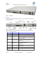
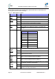
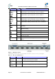
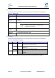
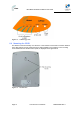
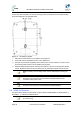
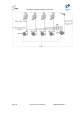
Table Of Contents
- 1.1 Purpose
- 1.4 Referenced Documentation
- 2.1 MicroMAX Frequency Ranges
- 2.2 System Components
- 2.3 Customer Benefits
- 2.4 Architecture
- 2.5 Power
- 2.6 Models
- 3.1 Package Contents
- 3.2 Required Tools
- 3.3 Radio Site Planning
- 4.1 MicroMAX BSR
- 4.2 SDA-4S Type II
- 4.3 SDA-4SDC Type II
- 5.1 Physical Dimensions
- 5.2 Ports
- 6.1 Physical Dimensions
- 6.2 Ports
- 6.3 LEDs
- 6.4 Mounting the GPSD
- 6.5 GPSD Architecture
- 7.1 Physical Dimensions
- 7.2 Ports
- 7.3 Crimping GPS Cable
- 7.4 Contact Socket Crimping
- 8.2 Redundant PS Unit
- 9.1 Pole-Mounting the BSR
- 9.2 Wall-Mounting the BSR (Optional)
- 9.3 Installing the SDA-4S
- 10.1 Desktop mounting
- 10.2 Rack mounting
- 12.1 Rack Mounting
- 12.2 Connecting Redundant PS Unit
- 13.1 Connecting the BSR to the SDA-4S
- 13.2 SDA-4S Type II
- 13.3 Connecting the BSR to BSDU
- 13.4 Connecting BSDU to Network
- 13.5 Connecting BSDUs
- 13.6 Connecting BSDU for SNMP Management
- 14.1 Connecting the SDA-4S Type II
- 14.2 Connecting the SDA-4SDC Type II
- 14.3 Connecting SDA-4S to Ethernet Network
- 15.1 Housing the Connectors
- 15.2 Connecting to the SDA-4SDC
- 16.1 Connections
- 16.2 Power Cable Assembly
- 16.3 Housing the Connectors
- 16.4 Cable Connection
- 17.1 Lightning Protection
- 17.2 Cable Preparation (for grounding)
- 17.3 FM Interference & ESD Protection Recommendations
- 17.4 Connecting Lightning and Surge Protector
- 17.5 Lightning and Surge Protection Connection Scenarios
- 18.1 Connecting GPS Antenna to BSDU
- 19.1 Environmental
- 19.2 Glossary of Terms
- 19.3 Revision History
- 19.4 Contact Information

MicroMAX Hardware Installation User Guide
Page 33 Commercial in Confidence UWB-D00068 Rev J
LED Status Description
On The link between the GE port and the backhaul or the daizy-
chained BSDU is synchronized with a rate of 100 Base-T
GE Ports
Status
Backhaul /
Cascade
10/100
(1–2)
Off The link between the GE port and the backhaul or the daizy-
chained BSDU is synchronized with a rate of 10 Base-T
On The link between the GE port and the backhaul or the daizy-
chained BSDU is synchronized with a rate of 1000 Base-T
GE Ports
Status
Backhaul /
Cascade
1000
(1–2)
Off The link between the GE port and the backhaul or the daizy-
chained BSDU is not synchronized with a rate of 1000 Base-T
On Master provides the GPS clock source in case of BSDUs
cascading
GPS Status
Master
Off Slave gets the GPS clock from the Master BSDU in case of
BSDUs cascading
On GPS is connected
GPS Status
GPS
Off No GPS is connected
Flashing When the GPS sync pulse is received
GPS Status
SYNC
Off No GPS sync pulse
Power
On Indicates whether the BSDU gets the -48 VDC from external
source
Figure 9 - BSDU Rear Panel
The following table lists the rear panel hardware interfaces (refer to the rear panel figure):
Table 14 - Rear panel Interfaces
Port Label Interface
15-pin D-type
female (8)
BSR 1 – BSR
8
Provides 10/100 Base-T (Ethernet),synchronization and 48
VDC power feed interfaces with BSRs
25-pin D-type
female
External
Power Supply
For external Power Supply (AC/DC) management
15-pin D-type
female (1)
GPS Global Positioning System (GPS)-based synchronization