
User's Manual
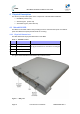
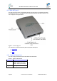
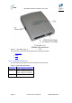
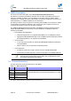
Table Of Contents
- 1.1 Purpose
- 1.4 Referenced Documentation
- 2.1 MicroMAX Frequency Ranges
- 2.2 System Components
- 2.3 Customer Benefits
- 2.4 Architecture
- 2.5 Power
- 2.6 Models
- 3.1 Package Contents
- 3.2 Required Tools
- 3.3 Radio Site Planning
- 4.1 MicroMAX BSR
- 4.2 SDA-4S Type II
- 4.3 SDA-4SDC Type II
- 5.1 Physical Dimensions
- 5.2 Ports
- 6.1 Physical Dimensions
- 6.2 Ports
- 6.3 LEDs
- 6.4 Mounting the GPSD
- 6.5 GPSD Architecture
- 7.1 Physical Dimensions
- 7.2 Ports
- 7.3 Crimping GPS Cable
- 7.4 Contact Socket Crimping
- 8.2 Redundant PS Unit
- 9.1 Pole-Mounting the BSR
- 9.2 Wall-Mounting the BSR (Optional)
- 9.3 Installing the SDA-4S
- 10.1 Desktop mounting
- 10.2 Rack mounting
- 12.1 Rack Mounting
- 12.2 Connecting Redundant PS Unit
- 13.1 Connecting the BSR to the SDA-4S
- 13.2 SDA-4S Type II
- 13.3 Connecting the BSR to BSDU
- 13.4 Connecting BSDU to Network
- 13.5 Connecting BSDUs
- 13.6 Connecting BSDU for SNMP Management
- 14.1 Connecting the SDA-4S Type II
- 14.2 Connecting the SDA-4SDC Type II
- 14.3 Connecting SDA-4S to Ethernet Network
- 15.1 Housing the Connectors
- 15.2 Connecting to the SDA-4SDC
- 16.1 Connections
- 16.2 Power Cable Assembly
- 16.3 Housing the Connectors
- 16.4 Cable Connection
- 17.1 Lightning Protection
- 17.2 Cable Preparation (for grounding)
- 17.3 FM Interference & ESD Protection Recommendations
- 17.4 Connecting Lightning and Surge Protector
- 17.5 Lightning and Surge Protection Connection Scenarios
- 18.1 Connecting GPS Antenna to BSDU
- 19.1 Environmental
- 19.2 Glossary of Terms
- 19.3 Revision History
- 19.4 Contact Information

MicroMAX Hardware Installation User Guide
Page 30 Commercial in Confidence UWB-D00068 Rev J
5 BSDU Description
This section provides a description of the Base Station Distribution Unit (BSDU).
The BSDU is connected to the BSRs by standard CAT-5e cables. Each BSDU can service a
maximum of 8 BSRs. In addition, up to two BSDUs can be daisy-chained at a Base Station,
supporting up to 16 BSRs. Therefore, a Base Station at maximum configuration can serve up to
8192 subscribers (i.e. 16 BSRs multiplied by 512 subscribers).
The BSDU provides a 15-pin D-type port for interfacing with the BSRs, for convenience, a DB15-
to-RJ45 adapter is supplied for attaching to the 15-pin D-type port to allow the use of RJ-45
connectors for outdoor-to-indoor CAT-5e cable connectivity.
The AIRSPAN WIMAX Base Station Distribution Unit (BSDU) provides an interface between
multiple MicroMAX (BSRs) and the service provider’s backbone. The BSDU provides the
following functionalities:
¾ Data switching and aggregation:
• Data switching between up to eight MicroMAX BSRs over 10/100 BaseT interface.
• Aggregate the MicroMAX BSRs data via two 1000BaseT Ethernet (GE) ports towards
the backhaul/backbone or to cascade to another BSDU.
¾ Synchronization:
• Tx / Rx TDD synchronization for multiple MicroMAX BSRs per BSDU and between
connected BSDUs.
• GPS for TDD Tx / Rx synchronization of different BS sites.
¾ Power distribution
• Provides DC power from a single -48 VDC source to eight MicroMAX BSRs.
• AC/DC power converter (optional) - in the event -48 VDC is not available at BS site.
Note: The unit should be powered by -48Vdc (40-54Vdc), 4.5A from safety
approved power supply that its output is SELV and is separated from mains
by minimum double/reinforced insulation.
5.1 Physical Dimensions
The table below lists the physical dimensions of the BSDU.
Table 11 - BSDU dimensions
Parameter Value Comment
Height 43.2 mm (1.7 inches)
Width 482.6 mm (19 inches)
Depth 228.6 mm (9 inches)
Weight 2.9 kg
The physical dimensions exclude the bracket flanges for mounting.
The figure below illustrates the BSDU's physical dimensions.