
User's Manual
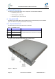
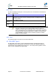
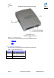
Table Of Contents
- 1.1 Purpose
- 1.4 Referenced Documentation
- 2.1 MicroMAX Frequency Ranges
- 2.2 System Components
- 2.3 Customer Benefits
- 2.4 Architecture
- 2.5 Power
- 2.6 Models
- 3.1 Package Contents
- 3.2 Required Tools
- 3.3 Radio Site Planning
- 4.1 MicroMAX BSR
- 4.2 SDA-4S Type II
- 4.3 SDA-4SDC Type II
- 5.1 Physical Dimensions
- 5.2 Ports
- 6.1 Physical Dimensions
- 6.2 Ports
- 6.3 LEDs
- 6.4 Mounting the GPSD
- 6.5 GPSD Architecture
- 7.1 Physical Dimensions
- 7.2 Ports
- 7.3 Crimping GPS Cable
- 7.4 Contact Socket Crimping
- 8.2 Redundant PS Unit
- 9.1 Pole-Mounting the BSR
- 9.2 Wall-Mounting the BSR (Optional)
- 9.3 Installing the SDA-4S
- 10.1 Desktop mounting
- 10.2 Rack mounting
- 12.1 Rack Mounting
- 12.2 Connecting Redundant PS Unit
- 13.1 Connecting the BSR to the SDA-4S
- 13.2 SDA-4S Type II
- 13.3 Connecting the BSR to BSDU
- 13.4 Connecting BSDU to Network
- 13.5 Connecting BSDUs
- 13.6 Connecting BSDU for SNMP Management
- 14.1 Connecting the SDA-4S Type II
- 14.2 Connecting the SDA-4SDC Type II
- 14.3 Connecting SDA-4S to Ethernet Network
- 15.1 Housing the Connectors
- 15.2 Connecting to the SDA-4SDC
- 16.1 Connections
- 16.2 Power Cable Assembly
- 16.3 Housing the Connectors
- 16.4 Cable Connection
- 17.1 Lightning Protection
- 17.2 Cable Preparation (for grounding)
- 17.3 FM Interference & ESD Protection Recommendations
- 17.4 Connecting Lightning and Surge Protector
- 17.5 Lightning and Surge Protection Connection Scenarios
- 18.1 Connecting GPS Antenna to BSDU
- 19.1 Environmental
- 19.2 Glossary of Terms
- 19.3 Revision History
- 19.4 Contact Information

MicroMAX Hardware Installation User Guide
Page 28 Commercial in Confidence UWB-D00068 Rev J
4.3.2 Ports
The SDA-4SDC adapter provides ports on the front panel, which are described in the table below:
Table 9 - SDA-4SDC ports
Port Interface
4 x 8-pin RJ-
45
10/100BaseT with subscriber's network (supports Auto Negotiation and
MDI/MDI-X automatic crossover, allowing connection of straight-through or
crossover cables)
15-pin D-type
(female)
10/100BaseT with BSR
DC power
socket
DC power outlet (10-52 VDC, 24W)
4.3.3 LEDs
The SDA-4S (all types) adapter provides LED indicators on the top panel, which are described in
the table below:
Table 10 - SDA-4S LEDs
LED Color Status Description
On Physical link (10BaseT or 100BaseT)
between SDA-4S adapter and BSR
Blinking Traffic currently flowing between SDA-4S and
BSR
UPLINK
Yellow (100BaseT) or
Orange (10BaseT)
Off No link between SDA-4S and BSR
On Physical link (10BaseT or 100BaseT)
between SDA-4S and subscriber's Ethernet
network
Blinking Traffic currently flowing between SDA-4S and
subscriber's Ethernet network
1, 2, 3,
4
Yellow (100BaseT) or
Orange (10BaseT)
Off No link between SDA-4S and subscriber's
Ethernet network
On Power received by SDA-4S
POWER Green
Off No power received by SDA-4S
The figure below displays the LEDs which are located on the top panel of the SDA-4S adapter: