
User's Manual
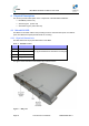
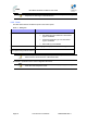
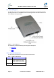
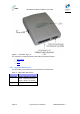
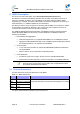
Table Of Contents
- 1.1 Purpose
- 1.4 Referenced Documentation
- 2.1 MicroMAX Frequency Ranges
- 2.2 System Components
- 2.3 Customer Benefits
- 2.4 Architecture
- 2.5 Power
- 2.6 Models
- 3.1 Package Contents
- 3.2 Required Tools
- 3.3 Radio Site Planning
- 4.1 MicroMAX BSR
- 4.2 SDA-4S Type II
- 4.3 SDA-4SDC Type II
- 5.1 Physical Dimensions
- 5.2 Ports
- 6.1 Physical Dimensions
- 6.2 Ports
- 6.3 LEDs
- 6.4 Mounting the GPSD
- 6.5 GPSD Architecture
- 7.1 Physical Dimensions
- 7.2 Ports
- 7.3 Crimping GPS Cable
- 7.4 Contact Socket Crimping
- 8.2 Redundant PS Unit
- 9.1 Pole-Mounting the BSR
- 9.2 Wall-Mounting the BSR (Optional)
- 9.3 Installing the SDA-4S
- 10.1 Desktop mounting
- 10.2 Rack mounting
- 12.1 Rack Mounting
- 12.2 Connecting Redundant PS Unit
- 13.1 Connecting the BSR to the SDA-4S
- 13.2 SDA-4S Type II
- 13.3 Connecting the BSR to BSDU
- 13.4 Connecting BSDU to Network
- 13.5 Connecting BSDUs
- 13.6 Connecting BSDU for SNMP Management
- 14.1 Connecting the SDA-4S Type II
- 14.2 Connecting the SDA-4SDC Type II
- 14.3 Connecting SDA-4S to Ethernet Network
- 15.1 Housing the Connectors
- 15.2 Connecting to the SDA-4SDC
- 16.1 Connections
- 16.2 Power Cable Assembly
- 16.3 Housing the Connectors
- 16.4 Cable Connection
- 17.1 Lightning Protection
- 17.2 Cable Preparation (for grounding)
- 17.3 FM Interference & ESD Protection Recommendations
- 17.4 Connecting Lightning and Surge Protector
- 17.5 Lightning and Surge Protection Connection Scenarios
- 18.1 Connecting GPS Antenna to BSDU
- 19.1 Environmental
- 19.2 Glossary of Terms
- 19.3 Revision History
- 19.4 Contact Information

MicroMAX Hardware Installation User Guide
Page 26 Commercial in Confidence UWB-D00068 Rev J
4.2.2 Ports
The SDA-4S adapter provides ports on the front panel, which are described in the table below:
Table 7 - SDA-4S ports
Port Interface
4 x 8-pin RJ-
45
10/100BaseT with subscriber's network (supports Auto Negotiation and
MDI/MDI-X automatic crossover, allowing connection of straight-through or
crossover cables)
15-pin D-type
(female)
10/100BaseT with BSR
AC power
socket
Subscriber's power outlet (110-240 VAC, 1A, 50/60 Hz, 50W)
Note: The ports of the SDA-4S models support Auto Negotiation, allowing
automatic configuration for the highest possible speed link (10BaseT or
100BaseT), and Full Duplex or Half Duplex mode. In other words, the speed
of the connected device (e.g. PC) determines the speed at which packets are
transmitted through the specific SDA-4S port. In addition, the SDA-4S ports
support MDI/MDI-X automatic crossover, allowing connection to straight-
through or crossover cables.
4.2.3 LEDs
The LEDs description is the same as for the SDA-4SDC below.
4.3 SDA-4SDC Type II
The SDA-4SDC Type II indoor unit is an integrated LAN switch, providing power and four
10/100BaseT ports for interfacing with the subscriber’s network and especially designed for
implementation where available power supply is DC. This model provides regulated –48 VDC
power. The unit is displayed in the figure below.