
User's Manual
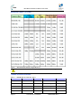
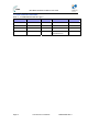
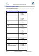
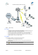
Table Of Contents
- 1.1 Purpose
- 1.4 Referenced Documentation
- 2.1 MicroMAX Frequency Ranges
- 2.2 System Components
- 2.3 Customer Benefits
- 2.4 Architecture
- 2.5 Power
- 2.6 Models
- 3.1 Package Contents
- 3.2 Required Tools
- 3.3 Radio Site Planning
- 4.1 MicroMAX BSR
- 4.2 SDA-4S Type II
- 4.3 SDA-4SDC Type II
- 5.1 Physical Dimensions
- 5.2 Ports
- 6.1 Physical Dimensions
- 6.2 Ports
- 6.3 LEDs
- 6.4 Mounting the GPSD
- 6.5 GPSD Architecture
- 7.1 Physical Dimensions
- 7.2 Ports
- 7.3 Crimping GPS Cable
- 7.4 Contact Socket Crimping
- 8.2 Redundant PS Unit
- 9.1 Pole-Mounting the BSR
- 9.2 Wall-Mounting the BSR (Optional)
- 9.3 Installing the SDA-4S
- 10.1 Desktop mounting
- 10.2 Rack mounting
- 12.1 Rack Mounting
- 12.2 Connecting Redundant PS Unit
- 13.1 Connecting the BSR to the SDA-4S
- 13.2 SDA-4S Type II
- 13.3 Connecting the BSR to BSDU
- 13.4 Connecting BSDU to Network
- 13.5 Connecting BSDUs
- 13.6 Connecting BSDU for SNMP Management
- 14.1 Connecting the SDA-4S Type II
- 14.2 Connecting the SDA-4SDC Type II
- 14.3 Connecting SDA-4S to Ethernet Network
- 15.1 Housing the Connectors
- 15.2 Connecting to the SDA-4SDC
- 16.1 Connections
- 16.2 Power Cable Assembly
- 16.3 Housing the Connectors
- 16.4 Cable Connection
- 17.1 Lightning Protection
- 17.2 Cable Preparation (for grounding)
- 17.3 FM Interference & ESD Protection Recommendations
- 17.4 Connecting Lightning and Surge Protector
- 17.5 Lightning and Surge Protection Connection Scenarios
- 18.1 Connecting GPS Antenna to BSDU
- 19.1 Environmental
- 19.2 Glossary of Terms
- 19.3 Revision History
- 19.4 Contact Information

MicroMAX Hardware Installation User Guide
Page 18 Commercial in Confidence UWB-D00068 Rev J
Frequency Band Channel Bandwidth
4.9 - 5.0 GHz in TDD mode ¾ 2.5 MHz
¾ 5 MHz
¾ 10 MHz
5.15 - 5.35 GHz in TDD mode ¾ 2.5 MHz
¾ 5 MHz
¾ 10 MHz
5.47 - 5.725 GHz in TDD mode ¾ 2.5 MHz
¾ 5 MHz
¾ 10 MHz
5.725 - 5.875 GHz in TDD mode ¾ 2.5 MHz
¾ 5 MHz
¾ 10 MHz
5.85 - 5.95 GHz in TDD mode ¾ 2.5 MHz
¾ 5 MHz
¾ 10 MHz
* As long as the central channel is an even number
2.2 System Components
¾ Outdoor - Unit(s):
• MicroMAX Base Station Radio(s) (BSR)
• Global Positioning System (GPS)
¾ Indoor:
• SDA-4S Type II: small low cost IDU with built in LAN switch
• SDA-4SDC Type II: small low cost DC IDU with built in LAN Switch
• GPSD: optional Global Positioning System Distribution unit (for up to 4 BSRs)
• BSDU: optional Ethernet switch for implementing Base Stations consisting of multiple
BSRs
¾ IDU/ODU connectivity:
• CAT-5e cable 24 gauge or better (22 gauge recommended) for connecting to BSR
(SFTP - Shielded Foiled Twisted Pair - recommended)
• Fast Ethernet: 4 pins
• VDC power: BSR FDD/TDD requires 2 pins
• IDU/ODU length for BSR FDD: up to 100 meters
¾ Minimum configuration:
• SDA-4S and a single BSR
¾ Larger configurations:
• N*SDA-4Ss and N*BSRs