
User's Manual
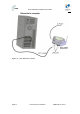
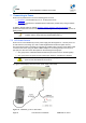
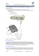
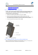

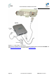
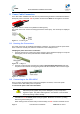


Table Of Contents
- 1.1 0BPurpose
- 1.4 1BReferenced Documentation
- 2.1 2BProST Frequency Ranges
- 2.2 3BProST-2 Frequency Ranges
- 2.3 4BArchitecture
- 2.4 5BModels
- 3.1 6BPackage Contents
- 3.2 7BMinimum PC Requirements
- 3.3 8BRequired Tools
- 3.4 9BRadio Site Planning
- 4.1 10BProST Physical Description
- 4.2 11BSDA-1 Physical Description
- 4.3 12BSDA-4S Type II and SDA-4S/VL Type II (Optional)
- 4.4 13BSDA-4SDC Type II (Optional DC power supply)
- 5.1 14BWall Mounting
- 5.2 15BPole-Mounting
- 5.3 16BMounting the SDA-4S
- 6.1 17BConnecting to IDU
- 6.2 18BConnecting to LAN Network
- 7.1 19BDC Power Source
- 7.2 20BConnecting the SDA-4SDC Type II (Optional DC adapter)
- 7.3 21BAC Power Source
- 8.1 22BHousing the Connectors
- 8.2 23BConnecting to the SDA-4SDC
- 9.1 24BPolyPhaser Wiring Diagram
- 9.2 25BLightning and Surge Protection Connection Scenarios
- 10.1 26BLED Status
- 12.1 27BTroubleshooting
- 12.2 28BGlossary of Terms
- 12.3 29BRevision History
- 12.4 30BContact Information

ProST Hardware Installation User Guide
Page 57 Commercial in Confidence UWB-D00111 Rev K
8 Power Cable Connection
In the SDA-4SDC installation Kit there are two polarized and genderless unassembled Anderson
Powerpole power connectors: red for positive connection and black for the negative connection.
Figure 46 - Power connectors (Anderson Powerpole)
The power connectors consist of housing (hood and a contact pins). The contact pin is displayed
below:
Figure 47 - Contact pin
8.1 Housing the Connectors
The power connectors are supplied unassembled. Therefore, you need to crimp the power wires
to the connector's contact pins, and then house them in the Powerpole hood.
Crimping the power wires to the connectors:
1. Insert the wire into the contact pin's barrel, and then, with a standard crimping tool crimp the
barrel tightly onto the wire (recommended 16 AWG cable wire).
Figure 48 – crimped
2. Insert the contact into the hood with the contact's tongue pointing downwards and snap
into place. Ensure that the housing spring mates with the underside of the contact's tongue.
Figure 49 – Insertion
8.2 Connecting to the SDA-4SDC
Once you have crimped the power cord to the Powerpole connectors, connect the power
connectors to the SDA-4SDC power receptacles.
To connect the power cord to the SDA-4SDC:
Caution: The plastic housings are held together with dovetail joints. Always
slide these joints together! They will be damaged if you try to snap them
together or apart. They ONLY slide together in one direction. This should be
obvious by looking at them carefully.
1. Assemble the red and black plastic housings together. Mate both connectors, by sliding
them along the dovetail joints.
When looking at the connector side (not the wire side), the red connector should be on the