
User's Manual
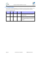
Table Of Contents
- 1.1 Purpose
- 1.4 Referenced Documentation
- 2.1 EasyST Frequency Ranges
- 2.2 Main Features
- 2.3 EasyST-2 Frequency Ranges
- 2.4 Main Features
- 2.5 Architecture
- 2.6 EasyST Protocol Stack
- 2.7 Theory of Operation
- 3.1 Package Contents
- 3.2 Minimum PC Requirements
- 3.3 Required Tools
- 4.1 Physical Dimensions
- 4.2 Ports
- 4.3 LEDs
- 4.4 LED Button
- 5.1 Connecting EasyST to a Computer
- 5.2 Connecting EasyST to Power
- 5.3 Verifying Correct Cabling
- 6.1 Desktop Mounting
- 6.2 Wall Mounting
- 8.1 Attaching the Antenna RF Cable
- 8.2 Mounting the External Antenna
- 13.1 Glossary of Terms
- 13.2 Revision History
- 13.3 Contact Information

EasyST Hardware Installation User Guide
Page 46 Commercial in Confidence UWB-D00128 Rev K
12 Troubleshooting
Once you have connected the EasyST to the subscriber's LAN and to the power supply, you can
verify whether you have cabled the EasyST correctly by checking the EasyST LED status:
Table 12 – Troubleshooting
Connection LED Color Correct
Status
Troubleshooting
Power
power Red
On If the power LED is off, recheck the
power cabling and that power exists at
the wall socket.
LAN
lan Green
On If the lan LED is off, recheck the LAN
cabling; ensure that you have connected it
to the correct LAN port on your PC and tha
t
your network connection on your PC is
enabled.