
User's Manual
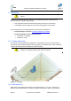
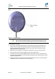
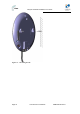
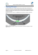
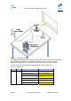
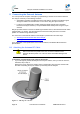
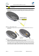
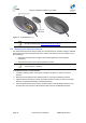
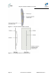
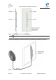
Table Of Contents
- 1.1 Purpose
- 1.4 Referenced Documentation
- 2.1 EasyST Frequency Ranges
- 2.2 Main Features
- 2.3 EasyST-2 Frequency Ranges
- 2.4 Main Features
- 2.5 Architecture
- 2.6 EasyST Protocol Stack
- 2.7 Theory of Operation
- 3.1 Package Contents
- 3.2 Minimum PC Requirements
- 3.3 Required Tools
- 4.1 Physical Dimensions
- 4.2 Ports
- 4.3 LEDs
- 4.4 LED Button
- 5.1 Connecting EasyST to a Computer
- 5.2 Connecting EasyST to Power
- 5.3 Verifying Correct Cabling
- 6.1 Desktop Mounting
- 6.2 Wall Mounting
- 8.1 Attaching the Antenna RF Cable
- 8.2 Mounting the External Antenna
- 13.1 Glossary of Terms
- 13.2 Revision History
- 13.3 Contact Information

EasyST Hardware Installation User Guide
Page 35 Commercial in Confidence UWB-D00128 Rev K
Figure 16 - Positioning EasyST
The signal LED indicates the strength of the signal by measuring the signal-to-noise ratio (SNR).
SNR indicates received signal strength relative to background noise. The ratio is usually
measured in decibels (dB). Thus, the higher the SNR ratio, the better the communication.
The table below describes the EasyST signal LEDs with regards to SNR values.
Table 11 - SNR values
LED Color Status Average SNR (dBm)
All LEDs are off SNR < 5
First left-most LED is on 5 <= Avg. SNR < 9
Two left-most LEDs are on 9 <= Avg. SNR < 12
Three left-most LEDs are on 12 <= Avg. SNR < 16
Four left-most LEDs are on 16 <= Avg. SNR < 22
signal Green
Five LEDs are on
22 <= Avg. SNR