
User's Manual
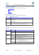
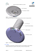
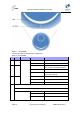
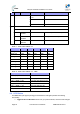
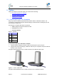
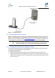
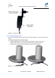
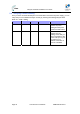
Table Of Contents
- 1.1 Purpose
- 1.4 Referenced Documentation
- 2.1 EasyST Frequency Ranges
- 2.2 Main Features
- 2.3 EasyST-2 Frequency Ranges
- 2.4 Main Features
- 2.5 Architecture
- 2.6 EasyST Protocol Stack
- 2.7 Theory of Operation
- 3.1 Package Contents
- 3.2 Minimum PC Requirements
- 3.3 Required Tools
- 4.1 Physical Dimensions
- 4.2 Ports
- 4.3 LEDs
- 4.4 LED Button
- 5.1 Connecting EasyST to a Computer
- 5.2 Connecting EasyST to Power
- 5.3 Verifying Correct Cabling
- 6.1 Desktop Mounting
- 6.2 Wall Mounting
- 8.1 Attaching the Antenna RF Cable
- 8.2 Mounting the External Antenna
- 13.1 Glossary of Terms
- 13.2 Revision History
- 13.3 Contact Information

EasyST Hardware Installation User Guide
Page 27 Commercial in Confidence UWB-D00128 Rev K
5 Cabling
Cabling your EasyST is fast and simple, and consists of the following:
¾ Connecting EasyST to a computer
¾ Connecting EasyST to power
¾ Verifying correct cabling
5.1 Connecting EasyST to a Computer
EasyST provides 10/100BaseT (Fast Ethernet) interface with the subscriber's network. The
connectivity is performed through the supplied Category 5 Ethernet cable consisting of 8-pin RJ-
45 connectors on either end.
The EasyST-to-computer cable setup is as follows:
¾ Cable: straight-through CAT 5 Ethernet cable
¾ Connector: 8-pin RJ-45
¾ Connector pinouts:
Table 9 – pinouts
Pin Function
1 Rx+
2 Rx-
3 Tx+
6 Tx-
To connect EasyST to the subscriber's network:
1. Plug the supplied Category 5 Ethernet cable into the EasyST's 8-pin RJ-45 port.
2. Plug the other end of the Category 5 Ethernet cable into your computer's LAN port located at
the back of your computer.
The figure below illustrates the CAT 5 cable connection to the EasyST's RJ-45 port:
Figure 8 - cable connection
The figure below illustrates the CAT 5 cable connection to the computer's LAN port: