
User's Manual
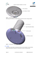
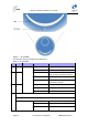
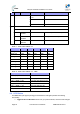
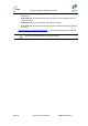
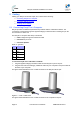
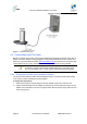
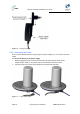
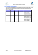
Table Of Contents
- 1.1 Purpose
- 1.4 Referenced Documentation
- 2.1 EasyST Frequency Ranges
- 2.2 Main Features
- 2.3 EasyST-2 Frequency Ranges
- 2.4 Main Features
- 2.5 Architecture
- 2.6 EasyST Protocol Stack
- 2.7 Theory of Operation
- 3.1 Package Contents
- 3.2 Minimum PC Requirements
- 3.3 Required Tools
- 4.1 Physical Dimensions
- 4.2 Ports
- 4.3 LEDs
- 4.4 LED Button
- 5.1 Connecting EasyST to a Computer
- 5.2 Connecting EasyST to Power
- 5.3 Verifying Correct Cabling
- 6.1 Desktop Mounting
- 6.2 Wall Mounting
- 8.1 Attaching the Antenna RF Cable
- 8.2 Mounting the External Antenna
- 13.1 Glossary of Terms
- 13.2 Revision History
- 13.3 Contact Information

EasyST Hardware Installation User Guide
Page 24 Commercial in Confidence UWB-D00128 Rev K
Figure 7 - EasyST LEDs
The EasyST LEDs are described in the table below:
Table 6 - EasyST LEDs
LED Color Mode Status Description
On EasyST receiving power power
Red
Off No power received by EasyST
On 10/100BaseT network device (e.g.
PC) correctly connected to EasyST
Flashing Active LAN link (i.e. traffic flow)
lan
Green
Off No 10/100BaseT interface
connected to EasyST
On Active WiMAX link
Flashing Undergoing Network Entry
link
Green
Off No WiMAX link
Customer mode
Average Signal to Noise Ratio (SNR)
All LEDs are off SNR < 5
First left-most LED is on 5 <= SNR < 9
signal
Green
Two left-most LEDs are
on
9 <= SNR < 12