
User's Manual
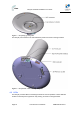
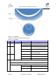
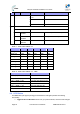
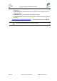
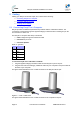
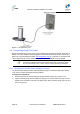
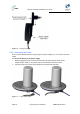
Table Of Contents
- 1.1 Purpose
- 1.4 Referenced Documentation
- 2.1 EasyST Frequency Ranges
- 2.2 Main Features
- 2.3 EasyST-2 Frequency Ranges
- 2.4 Main Features
- 2.5 Architecture
- 2.6 EasyST Protocol Stack
- 2.7 Theory of Operation
- 3.1 Package Contents
- 3.2 Minimum PC Requirements
- 3.3 Required Tools
- 4.1 Physical Dimensions
- 4.2 Ports
- 4.3 LEDs
- 4.4 LED Button
- 5.1 Connecting EasyST to a Computer
- 5.2 Connecting EasyST to Power
- 5.3 Verifying Correct Cabling
- 6.1 Desktop Mounting
- 6.2 Wall Mounting
- 8.1 Attaching the Antenna RF Cable
- 8.2 Mounting the External Antenna
- 13.1 Glossary of Terms
- 13.2 Revision History
- 13.3 Contact Information

EasyST Hardware Installation User Guide
Page 22 Commercial in Confidence UWB-D00128 Rev K
4 Physical Description
The EasyST's physical description is described in the following topics:
¾ Physical dimensions
¾ Ports
¾ LEDs
¾ LED Button
4.1 Physical Dimensions
The physical dimensions of the EasyST are listed in the table below:
Table 4 - EasyST physical dimensions
Parameter Value
Dimensions
(H x W x D):
¾ With clip-on antenna: 130 x 145 x 145 mm (5.12 x 5.7 x 5.7
inches)
¾ Without clip-on antenna: 30 x 145 x 145 mm (1.18 x 5.7 x 5.7
inches)
Weight:
¾ With clip-on antenna: 0.43 kg (approximate)
¾ Without clip-on antenna: 0.3 kg (approximate)
4.2 Ports
The EasyST provides various ports on its top, bottom, and side panels, as described in the table
below:
Table 5 - EasyST ports
Panel Port Interface
8-pin RJ-45 10/100BaseT Ethernet LAN
Side
DC power
jack
6 VDC power (supplied by AC/DC power adapter)
6-pin
header
Integrated Antenna Controller for attaching clip-on antenna
(determines active antenna--1 out of 4)
Top (cover
exposed)
MCX jack Clip-on antenna or window-mount external antenna
(connected by RF cable)
30-pin IDC
socket
Plug-in extension module for the following interfaces:
¾ 802.11 WiFi and LAN Switch
¾ VoIP and Battery Backup (EasyVoice)
Bottom
SIM Operator's defined parameters
The EasyST ports located on the top panel (with the clip-on antenna removed) are shown in the
figure below: