
User's Manual
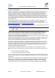
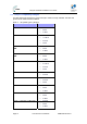
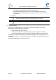
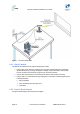
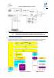
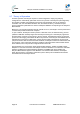
Table Of Contents
- 1.1 Purpose
- 1.4 Referenced Documentation
- 2.1 EasyST Frequency Ranges
- 2.2 Main Features
- 2.3 EasyST-2 Frequency Ranges
- 2.4 Main Features
- 2.5 Architecture
- 2.6 EasyST Protocol Stack
- 2.7 Theory of Operation
- 3.1 Package Contents
- 3.2 Minimum PC Requirements
- 3.3 Required Tools
- 4.1 Physical Dimensions
- 4.2 Ports
- 4.3 LEDs
- 4.4 LED Button
- 5.1 Connecting EasyST to a Computer
- 5.2 Connecting EasyST to Power
- 5.3 Verifying Correct Cabling
- 6.1 Desktop Mounting
- 6.2 Wall Mounting
- 8.1 Attaching the Antenna RF Cable
- 8.2 Mounting the External Antenna
- 13.1 Glossary of Terms
- 13.2 Revision History
- 13.3 Contact Information

EasyST Hardware Installation User Guide
Page 18 Commercial in Confidence UWB-D00128 Rev K
Figure 2 - EasyST architecture
2.5.1 EasyST Models
The EasyST is available in three optional deployment models:
¾ EasyST with clip-on antenna containing four high-gain, integrated flat panel, 90-degree
directional antennas, providing 360 degree coverage. EasyST selects the antenna with
best RF reception with the BS by using the 6-pin Antenna Controller.
¾ EasyST with external antenna connected by RF cable for easy window mounting.
¾ EasyST (clip on or external antenna) providing plug-in expansion modules supporting the
following interfaces:
• WiFi (EasyWiFi)
• VoIP and battery backup (EasyVoice)
• LAN switch
2.5.2 EasyST Block Diagram
The figure below displays the EasyST block diagram: