
User's Manual


Table Of Contents
- INTRODUCTION
- WARNINGS AND CAUTIONS
- DECLARATION OF CONFORMITY
- FCC INTERFERENCE STATEMENT
- SYSTEM OVERVIEW
- INSTALLATION PREREQUISITES
- PHYSICAL DESCRIPTION
- CABLING
- MOUNTING
- OPTIMIZING RF RECEPTION
- CONNECTING THE EXTERNAL ANTENNA
- REPLACING THE CLIP-ON ANTENNA
- EASYST SMART CARD
- RESETTING EASYST TO DEFAULT SETTINGS
- TROUBLESHOOTING
- TRADEMARKS AND COPYRIGHTS
- CONTACT INFORMATION
- REVISIONS
- WARNINGS
- GLOSSARY
- INDEX
605-0000-701 EasyST Hardware Installation User Guide Rev H
32
The signal LED indicates the strength of the signal by measuring the signal-to-noise ratio (SNR).
SNR indicates received signal strength relative to background noise. The ratio is usually measured
in decibels (dB). Thus, the higher the SNR ratio, the better the communication.
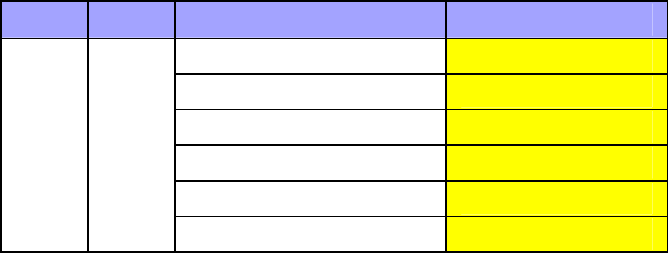
The table below describes the EasyST signal LEDs with regards to SNR values.
LED Color Status Average SNR (dBm)
All LEDs are off SNR < 5
First left-most LED is on 5 <= Avg. SNR < 9
Two left-most LEDs are on 9 <= Avg. SNR < 12
Three left-most LEDs are on 12 <= Avg. SNR < 16
Four left-most LEDs are on 16 <= Avg. SNR < 22
signal Green
Five LEDs are on
22 <= Avg. SNR