
User's Manual


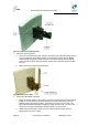
Table Of Contents
- 1 About this Guide
- 2 System Overview
- 3 Installation Prerequisites
- 4 Physical Description
- 5 Mounting the ProST
- 6 Network Cabling
- 7 Connecting to Power
- 8 Power Cable Connection
- 9 Connecting Lightning and Surge Protector
- 10 RSSI LED Plug Adapter for Antenna Alignment
- 11 Connecting External Antenna
- 12 Appendix

ProST Hardware Installation User Guide
Page 40 Commercial in Confidence UWB-D00111 Rev L
Figure25‐Polemountclampingbracket
3. Attach the U-bolt to the pole:
a. Place one U-bolt around the pole, and then insert the U-bolt screw side through the two
corresponding holes (horizontally parallel) on the clamping bracket. Slide an M8-flat
washer and M8-spring lock washer onto each U-bolt screw side (ensure that the flat
washer is adjacent to the clamping bracket). Fasten each U-bolt side with the two M8-
hex nuts.
b. Attach the second U-bolt as described above.
Figure26‐PolemountU‐bolts
4. Perform final MicroMAX orientation:
a. Adjust the vertical position of the ProST by choosing a final elevation hole as described
in Step 2. Lock the ProST at the desired position by inserting the locking bolt in the
desired position and fastening it tightly. Fasten tightly the bolt in the pivot hole. The
figure below illustrates the angles (in degrees) of each elevation hole. As shown, the
ProST pole-mounting bracket allows elevation between -18.5° and 26.3°.
b. Adjust the horizontal position of the ProST by rotating it about the pole, and then
tightening the nuts of the U-bolts.