
User's Manual


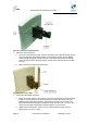
Table Of Contents
- 1 About this Guide
- 2 System Overview
- 3 Installation Prerequisites
- 4 Physical Description
- 5 Mounting the ProST
- 6 Network Cabling
- 7 Connecting to Power
- 8 Power Cable Connection
- 9 Connecting Lightning and Surge Protector
- 10 RSSI LED Plug Adapter for Antenna Alignment
- 11 Connecting External Antenna
- 12 Appendix

ProST Hardware Installation User Guide
Page 37 Commercial in Confidence UWB-D00111 Rev L
Figure20‐Mountingbracket
5. Attach the ProST to the mounting bracket by performing the following:
a) Slide an M10-spring lock washer and then an M10-plain washer onto each M10 x 1.5
hex head screw (20mm length) – (ensure lock washer is nearest to head of screw bolt).
b) Align the mounting bracket's holes with the ProST's mounting holes as displayed below.
(The mounting bracket side that provides a groove for inserting a nut must be aligned
with the ProST's mounting hole that is nearest to the ProST's rear panel.)
c) From the external sides, insert the M10-hex head screws through the mounting
bracket's holes and ProST's mounting holes. Loosely fasten with the M10-hex nuts.
Figure21‐Mountingtobracket
6. Adjust the horizontal positioning of the ProST, and then tighten the two M10 x 1.5-hex head
screws (20mm length) with the M10 hex nuts. Max torgue for M10 is 44Nm (32lbf.ft.).
Note: A third-party thread-locking compound must be applied to the M10-hex
head screws to prevent the bolts from working loose.
Rotation is restricted in the horizontal plane only, as shown in the figure below: