
User's Manual


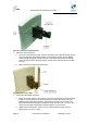
Table Of Contents
- 1 About this Guide
- 2 System Overview
- 3 Installation Prerequisites
- 4 Physical Description
- 5 Mounting the ProST
- 6 Network Cabling
- 7 Connecting to Power
- 8 Power Cable Connection
- 9 Connecting Lightning and Surge Protector
- 10 RSSI LED Plug Adapter for Antenna Alignment
- 11 Connecting External Antenna
- 12 Appendix

ProST Hardware Installation User Guide
Page 35 Commercial in Confidence UWB-D00111 Rev L
Figure17‐Mountseparation
The figure below illustrates the minimum separation between mounted ProST's when transmitting
on the same sector:
Figure18‐Mountseparation1
5.1 Wall Mounting
The ProST is wall mounted in two main stages:
¾ Attaching the mounting bracket to the ProST's mounting holes
¾ Attaching the mounting bracket (attached to the ProST) to the wall
To wall mount the ProST:
1. Position the unassembled mounting bracket on the mounting surface (e.g. wall), and then
use a pencil to mark the position of the four mounting holes. Ensure that the distance
between the hole centers are 120 mm (height) and 60 mm (width), as displayed in the figure
below showing the ProST's fixing dimensions.