
User Manual
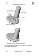
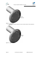
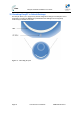
Table Of Contents
- 1.1 Purpose
- 1.4 Referenced Documentation
- 2.1 EasyST Frequency Ranges
- 2.2 Main Features
- 2.3 EasyST-2 Frequency Ranges
- 2.4 Main Features
- 2.5 Architecture
- 2.6 EasyST Protocol Stack
- 2.7 Theory of Operation
- 3.1 Package Contents
- 3.2 Minimum PC Requirements
- 3.3 Required Tools
- 4.1 Physical Dimensions
- 4.2 Ports
- 4.3 LEDs
- 4.4 LED Button
- 5.1 Connecting EasyST to a Computer
- 5.2 Connecting EasyST to Power
- 5.3 Verifying Correct Cabling
- 6.1 Desktop Mounting
- 6.2 Wall Mounting
- 8.1 Attaching the Antenna RF Cable
- 8.2 Mounting the External Antenna
- 13.1 Glossary of Terms
- 13.2 Revision History
- 13.3 Contact Information
EasyST Hardware Installation User Guide
Page 42 Commercial in Confidence UWB-D00128 Rev K
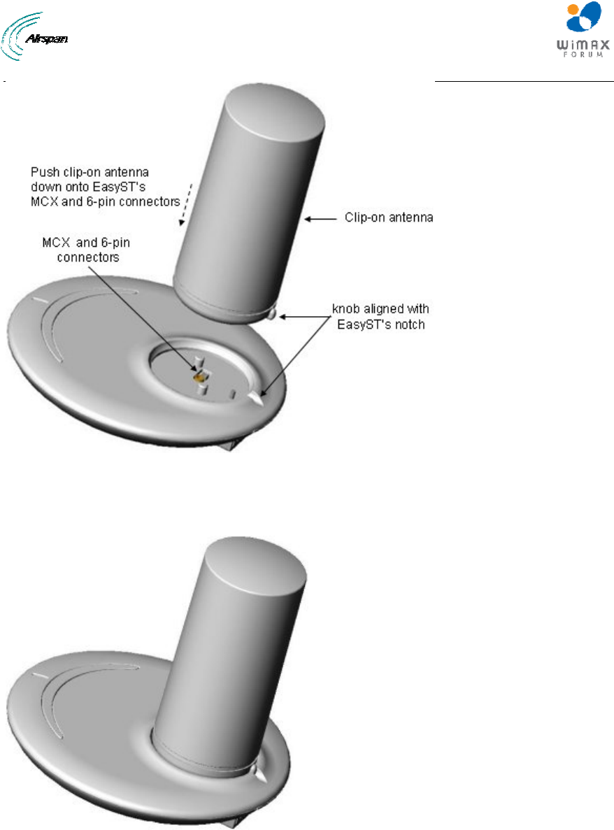
Figure 27 - clip-on antenna
4. Gently push the antenna down onto the EasyST so that the MCX and 6-pin connectors plug
into their respective receptacles, and that the antenna's knob sits firmly into the EasyST's
notch.
Figure 28 - antenna attached
5. For customers possessing EasyST models that implement a screw mechanism for securing
the antenna to the EasyST, continue with the following steps:
a. Flip the EasyST over so that its rear panel is visible. Insert the M3 25-mm flat-head Philips
screw (supplied) into the hole that's located on the rear panel, behind the RJ-45 and DC power
connectors, as shown in the figure below.