
User Manual
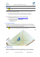
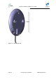
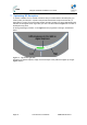
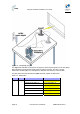
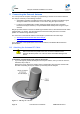
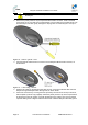
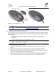
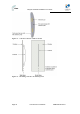
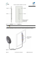
Table Of Contents
- 1.1 Purpose
- 1.4 Referenced Documentation
- 2.1 EasyST Frequency Ranges
- 2.2 Main Features
- 2.3 EasyST-2 Frequency Ranges
- 2.4 Main Features
- 2.5 Architecture
- 2.6 EasyST Protocol Stack
- 2.7 Theory of Operation
- 3.1 Package Contents
- 3.2 Minimum PC Requirements
- 3.3 Required Tools
- 4.1 Physical Dimensions
- 4.2 Ports
- 4.3 LEDs
- 4.4 LED Button
- 5.1 Connecting EasyST to a Computer
- 5.2 Connecting EasyST to Power
- 5.3 Verifying Correct Cabling
- 6.1 Desktop Mounting
- 6.2 Wall Mounting
- 8.1 Attaching the Antenna RF Cable
- 8.2 Mounting the External Antenna
- 13.1 Glossary of Terms
- 13.2 Revision History
- 13.3 Contact Information
EasyST Hardware Installation User Guide
Page 34 Commercial in Confidence UWB-D00128 Rev K
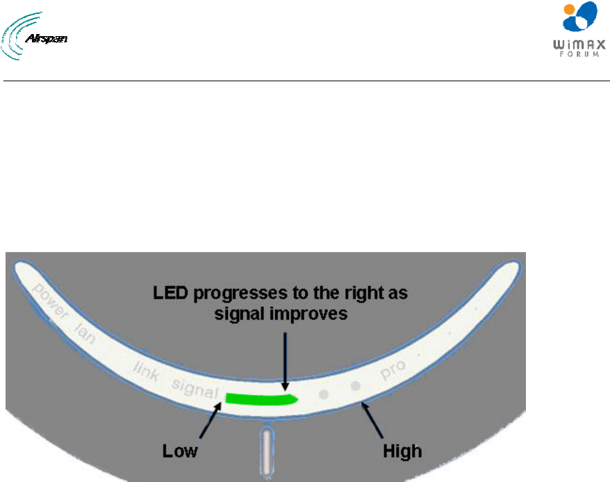
7 Optimizing RF Reception
To ensure a reliable, secure, and fast connection with your Internet Service Provider (ISP), you
need to place your EasyST in a position that provides the best RF reception with the ISP (i.e.
base station). To help you locate the best position, EasyST provides you with a LED indicator that
indicates the strength of the RF signal with your ISP. This LED is labeled signal and is located on
the EasyST's top panel.
As the signal strength increases, so the signal LED line progresses to the right, as illustrated
below:
Figure 15 - Signal strength LED
Therefore, for optimal reception, simply move the EasyST to the position that lights up a longer
signal LED line.