
User Manual
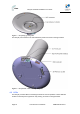
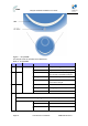
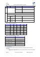
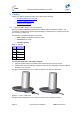
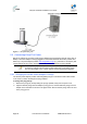
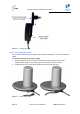
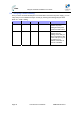
Table Of Contents
- 1.1 Purpose
- 1.4 Referenced Documentation
- 2.1 EasyST Frequency Ranges
- 2.2 Main Features
- 2.3 EasyST-2 Frequency Ranges
- 2.4 Main Features
- 2.5 Architecture
- 2.6 EasyST Protocol Stack
- 2.7 Theory of Operation
- 3.1 Package Contents
- 3.2 Minimum PC Requirements
- 3.3 Required Tools
- 4.1 Physical Dimensions
- 4.2 Ports
- 4.3 LEDs
- 4.4 LED Button
- 5.1 Connecting EasyST to a Computer
- 5.2 Connecting EasyST to Power
- 5.3 Verifying Correct Cabling
- 6.1 Desktop Mounting
- 6.2 Wall Mounting
- 8.1 Attaching the Antenna RF Cable
- 8.2 Mounting the External Antenna
- 13.1 Glossary of Terms
- 13.2 Revision History
- 13.3 Contact Information
EasyST Hardware Installation User Guide
Page 23 Commercial in Confidence UWB-D00128 Rev K
Figure 5 - EasyST top panel ports
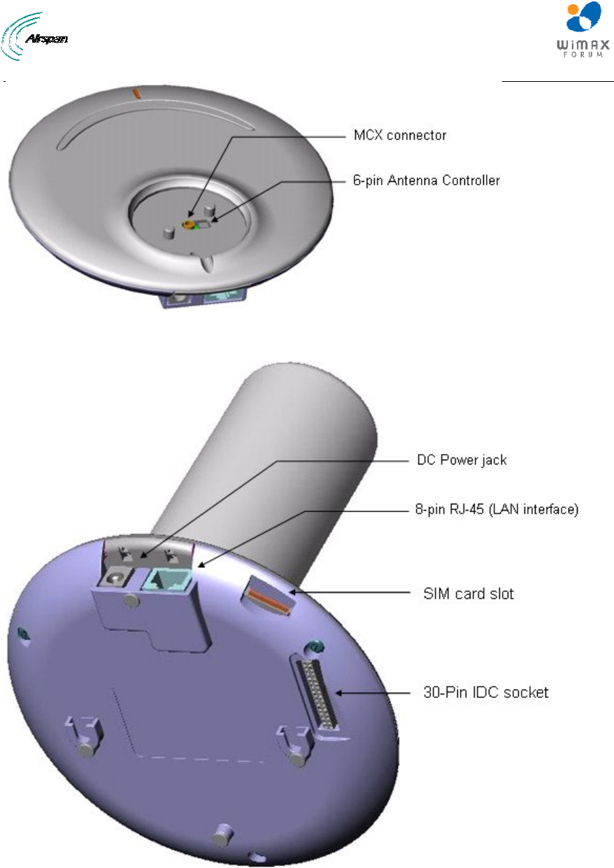
The EasyST ports located on the side and bottom panels are shown in the figure below:
Figure 6 - EasyST side and bottom panel ports
4.3 LEDs
The EasyST provides LEDs for indicating the status of various operations. These LEDs are
located on the EasyST's top panel for easy viewing, as shown in the figure below: