
User's Manual
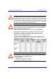
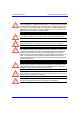
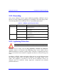
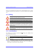
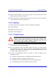
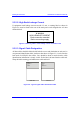
Table Of Contents
- Hardware Installation Guide
- Contents
- About this Guide
- 1. Overview
- 2. Safety Guidelines
- 3. Package Contents
- 4. Required Tools
- 5. Radio Site Planning
- Part I: Base Station Installation
- Part II: CPE Installation - Subscriber Premises Radio (SPR)
- Part III: CPE Installation - Indoor Data Radio Indoor (IDR)
- A. Glossary
- B. Installing the BSPS
- B.1. Basic Design
- B.2. Physical Dimensions
- B.3. Electrical Site Requirements
- B.4. BSPS Cabinet Cabling
- B.5. Installation Summary
- B.6. BSPS Batteries
- B.7. Rectifiers
- B.8. Operating the System Controller
- B.9. Powering on BSPS
- B.10. Connecting BSPS Management Cables
- B.11. Cabinet Power Requirements
- B.12. Troubleshooting
- C. Cable Crimping
- D. Connector Pinouts for SPR with DB9
- E. Evaluating Link Quality
- F. Technical Specifications
- G. Third-Party External Antenna Specifications
- H. Declaration of Conformity
Safety Guidelines Hardware Installation Guide
2-10 Airspan Networks Inc. 02030311-07
2.3.2.2. High Earth Leakage Current
If equipment earth leakage current exceeds 3.5 mA, a warning label as shown in
Figure 2-1 must be fitted to the rear of the main power rack alongside the AC inlet
terminal block.
Figure 2-1: Warning label if earth leakage current exceeds 3.5 mA
2.3.2.3. Signal Cable Designation
All data cables should be labeled with both the source and destination at each end. A
wrap around identification label, similar to that shown in Figure 2-2, is to be fitted to
both ends of ASWipLL data cables. Care should be taken to ensure that the cable
identification information is clearly visible. Fit the label 100 mm from the cable end.
Wrap the label ensuring good adhesion to cable and itself.
From
BDSU 1/1
To
SPR 1
To
SPR 1
From
BDSU 1/1
BSDU End
SPR End
Figure 2-2: Typical signal cable identification label
WARNING
HIGH LEAKAGE CURRENT
Earth connection essential
Before connecting supply