
User's Manual
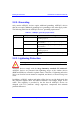
Table Of Contents
- Hardware Installation Guide
- Contents
- About this Guide
- 1. Overview
- 2. Safety Guidelines
- 3. Package Contents
- 4. Required Tools
- 5. Radio Site Planning
- Part I: Base Station Installation
- Part II: CPE Installation - Subscriber Premises Radio (SPR)
- Part III: CPE Installation - Indoor Data Radio Indoor (IDR)
- A. Glossary
- B. Installing the BSPS
- B.1. Basic Design
- B.2. Physical Dimensions
- B.3. Electrical Site Requirements
- B.4. BSPS Cabinet Cabling
- B.5. Installation Summary
- B.6. BSPS Batteries
- B.7. Rectifiers
- B.8. Operating the System Controller
- B.9. Powering on BSPS
- B.10. Connecting BSPS Management Cables
- B.11. Cabinet Power Requirements
- B.12. Troubleshooting
- C. Cable Crimping
- D. Connector Pinouts for SPR with DB9
- E. Evaluating Link Quality
- F. Technical Specifications
- G. Third-Party External Antenna Specifications
- H. Declaration of Conformity
Hardware Installation Guide Safety Guidelines
02030311-07 Airspan Networks Inc. 2-9
! Silicone sealant should be used to plug any holes on both internal and external
wall surfaces once cables are in place.
! Cables not housed in conduits must be placed in a manner to avoid a trip hazard.
(Avoid trailing wires across passageways.)
2.3.2. Labeling
The following labels are required to be fitted to ASWipLL equipment:
! Voltage Warning
! High Earth Leakage Current
! Signal Cable Designation
2.3.2.1. Voltage Warning
Warning: Voltages over 30 Volts AC and 50 Volts DC are categorized as
hazardous. Hazard warning labels should be fitted where required. Certain
countries require equipment warning and instruction labels to appear in the
local language. When installing ASWipLL equipment ensure that local
requirements regarding labels are given consideration.
! Where mains power is fed from separate phases, appropriate warning labels must
be fitted to warn of the increased danger.
! The AC equipment used in the BSPS cabinet must carry a relevant voltage
warning label specific to the country in which it is being installed. The label will
be fitted to the cabinet doors displaying an electrical hazard symbol, the local
operating voltage and the letters ‘AC’.
! A power feed identification label (e.g. PWR ‘A’) shall be applied in the
following locations:
! On the rear of the main power rack adjacent to the terminal block
! Attached to BSPS AC mains power plug or lead
! Attached to the customer mains power socket or distribution rail
! On the BSPS power circuit connection at the fuse board