
User's Manual
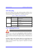
Table Of Contents
- Hardware Installation Guide
- Contents
- About this Guide
- 1. Overview
- 2. Safety Guidelines
- 3. Package Contents
- 4. Required Tools
- 5. Radio Site Planning
- Part I: Base Station Installation
- Part II: CPE Installation - Subscriber Premises Radio (SPR)
- Part III: CPE Installation - Indoor Data Radio Indoor (IDR)
- A. Glossary
- B. Installing the BSPS
- B.1. Basic Design
- B.2. Physical Dimensions
- B.3. Electrical Site Requirements
- B.4. BSPS Cabinet Cabling
- B.5. Installation Summary
- B.6. BSPS Batteries
- B.7. Rectifiers
- B.8. Operating the System Controller
- B.9. Powering on BSPS
- B.10. Connecting BSPS Management Cables
- B.11. Cabinet Power Requirements
- B.12. Troubleshooting
- C. Cable Crimping
- D. Connector Pinouts for SPR with DB9
- E. Evaluating Link Quality
- F. Technical Specifications
- G. Third-Party External Antenna Specifications
- H. Declaration of Conformity
Hardware Installation Guide Safety Guidelines
02030311-07 Airspan Networks Inc. 2-7
However, for geographical areas that have above normal lightening activity, Airspan
can supply a surge protector composed of a 15-pin D-type adapter with a grounding
wire.
2.3. Cabling
Warning: The maximum cable length between the radio transmitters (i.e. BSR
and SPR) and terminating equipment is 100 meters.
Warning: Cables with exposed ends (i.e. not yet crimped) should be covered
with protective polythene bags during external cable installation processes.
Warning: Prior to the commencement of any installation, commissioning work
at ‘live’ sites it is the responsibility of the Airspan engineer to advise the
customers representative before any activity commences. If in doubt assume
equipment is ‘live’.
Warning: Disturbance of cables on an In-Service exchange can cause loss o
f
service. Extreme care must be taken when installing cables at any customer o
r
subscriber premises.
2.3.1. Considerations
The following issues should be considered during cabling at the ASWipLL Base
Station and customer premises:
! Cable routes are to be defined in the site-specific documentation.
Note: A minimum separation of 200 mm should exist between power and data
cables. However, it is permissible to allow these cables to cross each other at
right angles.
! Observe recommended minimum bend radii when installing copper cables.
Wherever a cable changes direction, ensure that it does so in a smooth curve
with a radius of at least 50 mm to prevent damage.