
User's Manual
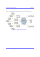
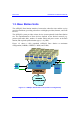
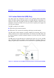
Table Of Contents
- Hardware Installation Guide
- Contents
- About this Guide
- 1. Overview
- 2. Safety Guidelines
- 3. Package Contents
- 4. Required Tools
- 5. Radio Site Planning
- Part I: Base Station Installation
- Part II: CPE Installation - Subscriber Premises Radio (SPR)
- Part III: CPE Installation - Indoor Data Radio Indoor (IDR)
- A. Glossary
- B. Installing the BSPS
- B.1. Basic Design
- B.2. Physical Dimensions
- B.3. Electrical Site Requirements
- B.4. BSPS Cabinet Cabling
- B.5. Installation Summary
- B.6. BSPS Batteries
- B.7. Rectifiers
- B.8. Operating the System Controller
- B.9. Powering on BSPS
- B.10. Connecting BSPS Management Cables
- B.11. Cabinet Power Requirements
- B.12. Troubleshooting
- C. Cable Crimping
- D. Connector Pinouts for SPR with DB9
- E. Evaluating Link Quality
- F. Technical Specifications
- G. Third-Party External Antenna Specifications
- H. Declaration of Conformity

Hardware Installation Guide Overview
02030311-07 Airspan Networks Inc. 1-7
1.3.6. Base Station Power Supply (BSPS) - Optional
The BSPS is an optional third-party unit that is implemented at Base Stations to
provide –48 VDC power supply and power redundancy. The BSPS is installed in a
standard 19-inch cabinet and connected to the BSDU.
The BSPS provides the BSDUs and BSRs with the following:
! Power supply of –48 VDC.
! Power redundancy in case of power failure. The BSPS charges a battery bank
that provides this power redundancy during mains failure. Thus, the BSPS acts
as a DC-uninterruptible power supply (UPS) with a battery connected to it. The
size of the battery determines the backup and charging time. Since the system is
current limited, the maximum battery size is based on that limit.
! Remote power management and monitoring (by ASWipLL’s WipManage
program).
The BSPS consists of the following basic components:
! Main unit:
! DC Rectifier modules: converts AC current to DC. The BSPS can house up
to four rectifiers. The rectifiers are “hot plugged” and operate in parallel.
This enables the user to define an N+1or N+2 redundant system. Each
rectifier has its own current sharing system, satisfying a complete sharing
among rectifiers.
! System controller: provides BSPS management control and BSPS operating
information.
! Electronic Low Voltage Detector (ELVD): disconnects the battery from
the load, avoiding damage to the battery when over-discharged.
! Load and battery circuit breakers: provide DC protection and distribution.
! DC Distribution unit: provides circuit breakers for distributing the output
current to multiple BSDUs. It also contains a bypass switch to bypass the LVD.
! Battery: provides the BSPS system with back-up power.