
User's Manual
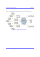
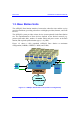
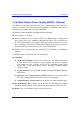
Table Of Contents
- Hardware Installation Guide
- Contents
- About this Guide
- 1. Overview
- 2. Safety Guidelines
- 3. Package Contents
- 4. Required Tools
- 5. Radio Site Planning
- Part I: Base Station Installation
- Part II: CPE Installation - Subscriber Premises Radio (SPR)
- Part III: CPE Installation - Indoor Data Radio Indoor (IDR)
- A. Glossary
- B. Installing the BSPS
- B.1. Basic Design
- B.2. Physical Dimensions
- B.3. Electrical Site Requirements
- B.4. BSPS Cabinet Cabling
- B.5. Installation Summary
- B.6. BSPS Batteries
- B.7. Rectifiers
- B.8. Operating the System Controller
- B.9. Powering on BSPS
- B.10. Connecting BSPS Management Cables
- B.11. Cabinet Power Requirements
- B.12. Troubleshooting
- C. Cable Crimping
- D. Connector Pinouts for SPR with DB9
- E. Evaluating Link Quality
- F. Technical Specifications
- G. Third-Party External Antenna Specifications
- H. Declaration of Conformity
Overview Hardware Installation Guide
1-4 Airspan Networks Inc. 02030311-07
1.3. Base Station Units
The ASWipLL Base Station interfaces between the subscriber sites and the service
provider's backbone, providing subscribers with high-speed data, Internet, and VoIP
services.
The ASWipLL system provides various devices (some optional) for the Base Station
site. The implementation of these devices depends on the desired network (e.g.
point-to-point radio link), number of outdoor radios and power source at the Base
Station, and required synchronization type (i.e. by GPS).
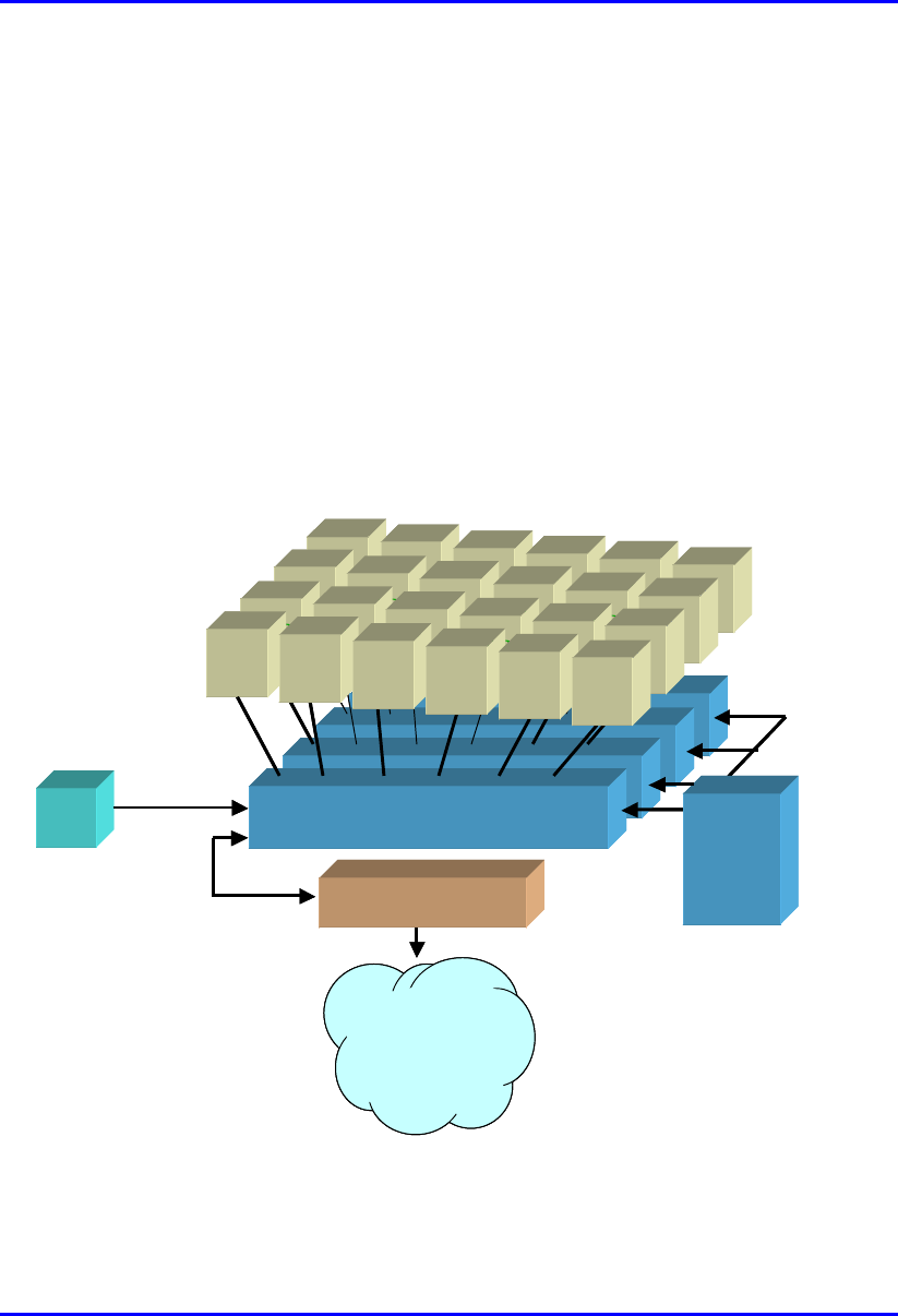
Figure 1-2 shows a fully populated ASWipLL Base Station at maximum
configuration (24 BSRs, 4 BSDUs, 1 BSPS, and a GPS).
BSR
BSDU
BSR
BSR
BSR
BSR
BSR
BSR
BSDU
BSR
BSR
BSR
BSR
BSR
BSR
BSDU
BSR
BSR
BSR
BSR
BSR
BSR
BSRBSR
BSR
BSDU
BSDUBSDU
BSDU
-
--
-48
4848
48 VDC
VDCVDC
VDC
100
100100
100B
BB
BaseT
aseTaseT
aseT
BSPS
BSPSBSPS
BSPS
BSR
BSRBSR
BSR
BSR
BSRBSR
BSR
BSR
BSRBSR
BSR
BS
SS
SR
BSR
BSRBSR
BSR
GPS
GPSGPS
GPS
Backbone
BackboneBackbone
Backbone
(
((
(IP, ATM,FR, MPLS
IP, ATM,FR, MPLSIP, ATM,FR, MPLS
IP, ATM,FR, MPLS)
))
)
Interface unit
Interface unit Interface unit
Interface unit
(
((
(e
ee
e.
..
.g
gg
g.
. .
. router, switch
router, switchrouter, switch
router, switch)
))
)
BSR
BSDU
BSR
BSR
BSR
BSR
BSR
BSR
BSDU
BSR
BSR
BSR
BSR
BSR
BSR
BSDU
BSR
BSR
BSR
BSR
BSR
BSR
BSRBSR
BSR
BSDU
BSDUBSDU
BSDU
-
--
-48
4848
48 VDC
VDCVDC
VDC
100
100100
100B
BB
BaseT
aseTaseT
aseT
BSPS
BSPSBSPS
BSPS
BSR
BSRBSR
BSR
BSR
BSRBSR
BSR
BSR
BSRBSR
BSR
BS
SS
SR
BSR
BSRBSR
BSR
GPS
GPSGPS
GPS
Backbone
BackboneBackbone
Backbone
(
((
(IP, ATM,FR, MPLS
IP, ATM,FR, MPLSIP, ATM,FR, MPLS
IP, ATM,FR, MPLS)
))
)
Interface unit
Interface unit Interface unit
Interface unit
(
((
(e
ee
e.
..
.g
gg
g.
. .
. router, switch
router, switchrouter, switch
router, switch)
))
)
Figure 1-2: ASWipLL Base Station units (maximum configuration)