
User's Manual


Network Cabling Hardware Installation Guide
14-2 Airspan Networks Inc. 02030311-10
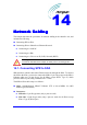
Connector pinouts:
Table 14-1: SPR-to-SDA connector pinouts
Straight-through cable
SPR SDA
15-pin
D-type
male
Pin Function
Wire color
Wire
pair
Pin Function
15-pin
D-type
male
/RJ-45
1 +48 VDC Blue / White 1 +48 VDC
2 48 RTN
Blue
1
2 48 RTN
3
Tx+
Orange /
White
3
Rx+
4 Tx-
Orange
2
4 Rx-
5
Rx+
Green /
White
5
Tx+
6 Rx-
Green
3
6 Tx-
Notes:
• The connector pinouts are the same for all SDA models.
• Only pins 1 through 6 are used.
• The wire color-coding is ASWipLL's standard for wire color-coding (for a detailed description of
ASWipLL's wire color-coding standard, see Appendix C, "Cable Crimping"). However, if you
implement your company's wire color-coding scheme, ensure that the wires are paired and twisted
according to the pin functions (e.g. Rx+ with Rx-) listed in the table above.
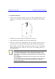
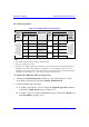
To connect the SPR to the SDA (see Figure 14-1):
1. Connect the 15-pin D-type male connector, at one end of the CAT 5 cable,
to the SPR's 15-pin D-type port labeled DATA POWER SYNC.
2. Connect the other end to the SDA:
For SDA except SDA-1 Type II: connect the 15-pin D-type male connector
to the SDA's 15-pin D-type port (see Figure 14-1)
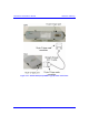
For SDA-1 Type II: connect the RJ-45 connector to the SDA's RJ-45 port
labeled RADIO (see Figure 14-2)