
User's Manual


Installing the BSR Hardware Installation Manual
4-12 Airspan Networks Ltd. 02030311-03
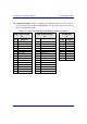
! SDA models (SDA-1, SDA-4H, and SDA-4S):
SDA
(15 Pin D-type)
Pin Function
1 +48VDC
2 -48VDC
3 +RX
4
–
RX
5 +TX
6
–
TX
7
N
C
8
N
C
9
N
C
10
N
C
11
N
C
12
N
C
13
N
C
14
N
C
15
N
C
Note: Airspan supplies unterminated cables for 15-Pin D-type connectors. Refe
r
to the cable crimping procedures for 15-Pin D-type connectors detailed in
Appendix B, “Cable Crimping".
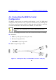
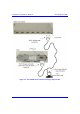
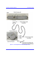
To connect the BSR to the backhaul through the SDA:
1. Attach the 15-pin D-type connector, at one end of the cable, to the BSR’s 15-pin
D-type port labeled DATA POWER SYNC, as displayed in Figure 4-6.
2. Attach the 15-pin D-type connector, at the other end of the cable, to the SDA’s
15-pin D-type port, as displayed in Figure 4-6.
3. Connect the SDA’s RJ-45 Ethernet port to the backhaul.
Note: SDA is available in six models. For a detailed description of the SD
A
models, see Chapter 8, “Installing the SPR and SDA”.