
User's Manual


Hardware Installation Manual Installing the BSR
02030311-03 Airspan Networks Ltd. 4-3
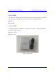
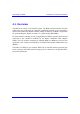
4.2. Physical Dimensions and Basic Design
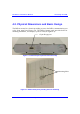
The BSR is encased in a chassis providing access to the BSR’s communication port
at the front panel (see Figure 4-1). The BSR’s bottom panel provides holes for
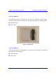
mounting the BSR to, for example, a pole or wall (see Figure 4-2).
Figure 4-1: BSR front panel (internal antenna model)
Figure 4-2: BSR bottom panel providing holes for mounting
15-pin D-type port
Mounting holes