
User's Manual


Hardware Installation Manual Installing and Configuring the IDR
02030311-03 Airspan Networks Ltd. 10-13
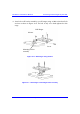
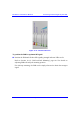
Figure 10-11: IDR LED indicators
To position the IDR for optimum RF signal:
! Position the IDR until all three RF signaling strength indicator LEDs are lit.
Refer to Section 10.1.2, “Wall and Pole Mounting” page 10-6 for details on
adjusting IDR wall and pole mounting position.
For desk-top mounting, the IDR can be simply relocated to obtain the strongest
signal.