
User's Manual Part 2b

Hardware Installation Guide Installing the BSPS
02030311-05 Airspan Networks Ltd. 7-9
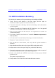
7.2. BSPS Installation Summary
The following is a summary of the procedural steps for installing the BSPS:
1. Verify that the circuit breakers of the load, battery and line input are
disconnected and the system is not connected to the line.
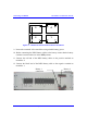
2. Connect the main unit to the battery and load via the Battery and Load terminals
on the rear panel.
3. Connect (if needed) the Extension and DC Distribution units.
Pay special
attention to the polarities of the wires and locations.
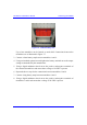
4. Insert a rectifier module into the main unit. All compartments are similar and
connected in parallel.
5. Use 16mm
2
(5 AWG) wires for the AC terminals. Minimum requirement is
8mm
2
(8 AWG)
6. AC source must be current limited (50A) using an external circuit breaker.
7. Plug the AC input cord into the AC source.
8. Turn on the Line circuit breaker, and verify that the system controller is
activated.
9. Insert the other rectifiers, and verify all green LED's on the panels are lit.
10. All parameters such as the output voltage are pre-defined in the factory.
11. Connect the temperature sensors to the appropriate connector at the rear panel of
the main unit. Place the sensors in the battery compartment.
12. Switch on the
LOAD and BATTERY circuit breakers. Verify that the BYPASS
breakers are off.
The system is now ready for use.
13. Verify that the
FAULT red LED is not lit and the buzzer not active.