
User's Manual Part 2b

Installing the GPS Hardware Installation Guide
6-4 Airspan Networks Ltd. 02030311-05
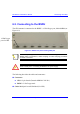
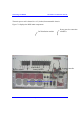
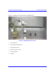
! Connector pinouts: The GPS connector receptacle contains 12 male contacts, as
displayed in Figure 6-3.
Figure 6-3: GPS connector pinouts
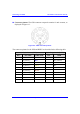
The connector pinouts for the GPS and BSDU are described in the following table.
12-pin female (GPS) 15-pin D-type male (BSDU)
Pin Pin name Cable color Pin Lead
1 POWER
Red
9
2 RX_DATA_1-
Blue
5 TD+ (after R5)
3 RX_DATA_1+
Black
6 TD-
4 TX_DATA_1-
Yellow
4 RD-
5 TX_DATA_1+
Black
3 RD+ (after R3)
6 RX_DATA_2-
Brown
x
7 RX_DATA_2+
Black
x
9 GND
Black
10
11 1PPS+
Green
8 1PPS-
12 1PPS-
Black
7 1PPS+ (After R7)