
User's Manual Part 2a

Hardware Installation Guide Installing the BSDU
02030311-05 Airspan Networks Ltd. 5-7
5.4. Connecting to BSRs
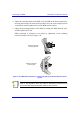
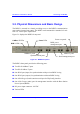
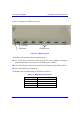
The BSDU rear panel provides six 15-Pin D-type connectors for connecting a
maximum of six BSRs. For a detailed description of connecting BSRs to the BSDU,
see Chapter 4, “Installing the BSR”.
Note: A maximum of 4 BSDUs can be installed at a base station, allowing
maximum connection of up to 24 BSRs.
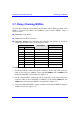
! Connector: 15-Pin D-type (male)
! Connector pinouts: see Chapter 4, “Installing the BSR”.
For a description of the BSDU’s BSR ports LED indicators, see Section 5.13.1,
“BSR’s LED”.
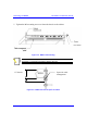
5.5. Connecting to the GPS Antenna
The rear panel of the BSDU provides a 15-Pin D-type connector port, labeled GPS
for connection to the GPS antenna for clock synchronization. The GPS allows
synchronization between base stations.
Note: For a detailed explanation on connecting the GPS to the BSDU port,
see Chapter 6, “Installing the GPS”.