
User's Manual Part 2a

Hardware Installation Guide Installing the BSDU
02030311-05 Airspan Networks Ltd. 5-3
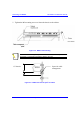
5.2. Physical Dimensions and Basic Design
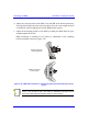
The BSDU is encased in a chassis providing access to the BSDU's communication
ports on the front and rear panels. The BSDU can be mounted in a standard 19" rack
with 1-U vertical space requirement.
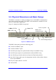
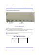
Figure 5-1 displays the BSDU's front panel.
Figure 5-1: BSDU front panel
The BSDU's front panel provides the following ports:
! Two RJ-45 100Base-T ports
! Two RJ-45 10Base-T ports
! One RJ-45 port (input) for synchronization with previous BSDU in ring
! One RJ-45 port (output) for synchronization with next BSDU in ring
! One 9-Pin D-type (female) monitor serial port for WipConfig interface
! One 9-Pin D-type (male) port for management interface with the Base Station
Power System (BSPS)
! DC power input connector –48 VDC
! Various LEDs
BSR’s LEDs
100Base-T LEDs Status LEDs
Power receptacle
BSPS power
management port
10Base-T ports
Serial management port
Synchronization ports
100Base-T ports