
User's Manual Part 2a


Installing the BSR Hardware Installation Guide
4-10 Airspan Networks Ltd. 02030311-05
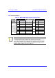
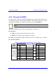
! Connector pinouts:
Table 4-3: BSR-to-SDA 15-pin D-type connector pinouts
BSR SDA 15-pin
D-type
male
Pin Function
Wire color Wire
pair
Pin Function
1 +48 VDC Blue / white 1 +48 VDC
2 -48 VDC Blue
1
2 -48 VDC
3 Tx+ Orange / white 3 Rx+
4 Tx- Orange
2
4 Rx-
5 Rx+ Green / white 5 Tx+
6 Rx- Green
3
6 Tx-
7 Sync.+ Brown / white 7 Sync.+
8 Sync.- Brown
4
8 Sync.-
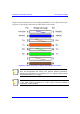
Notes:
- Pins 9 through 15 of the 15-pin D-type connector are not used.
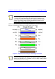
- The wire color-coding described in the table is WipLL's standard for wire
color-coding. However, if you implement your company's wire color-coding
scheme, ensure that the wires are paired and twisted according to the pin
functions listed in Table 4-3 (e.g., Rx+ with Rx-).