
User's Manual Part 2a


Hardware Installation Guide Installing the BSR
02030311-05 Airspan Networks Ltd. 4-7
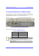
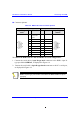
! Connector pinouts:
Table 4-2: BSR-to-PC serial connector pinouts
BSR PC
9-pin D-type
male
Pin Function Pin Function 9-pin D-type
female
1
Not
connected
(NC)
1 NC
2 RS232 Rx 3 Tx
3 RS232 Tx 2 Rx
4 NC 6 NC
5 GND 5 GND
6 NC 4 NC
7 NC 8 NC
8 NC 7 NC
9 NC 9 NC
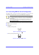
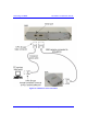
To connect the BSR to the PC and SDA/BSDU for serial configuration:
1. Connect the serial cable’s 9-pin D-type male connector to the BSR’s 9-pin D-
type port labeled SERIAL, as displayed in Figure 4-4.
2. Connect the serial cable’s 9-pin D-type female connector to the PC’s serial port,
as displayed in Figure 4-4.
Note: Ensure that the BSR remains connected to the BSDU/SDA (i.e., the
BSR’s 15-pin D-type port remains connected to the BSDU’s/SDA’s 15-pin D-
type port).