
User's Manual Chapter 10

Installing the IDR Hardware Installation Guide
10-18 Airspan Networks Ltd. 02030311-06
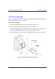
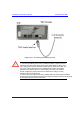
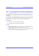
10.5.1. Ethernet LED Indicator
The IDR provides one LED that indicates an Ethernet connection. This LED is
labeled Ethernet and is located on the IDR’s top panel.
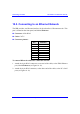
Table 10-2: Description of Ethernet LEDs
LED Color Status Indicates
On Physical link between IDR and Ethernet network
Off No physical link between IDR and Ethernet network
Ethernet Orange
Blinking Data is flowing through the Ethernet port
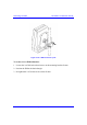
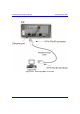
10.6. Positioning IDR for Optimum RF
Reception
Once mounted to a wall, pole, or desk the IDR unit may be positioned to ensure the
best RF signal communication with the BSR. The RF signal strength is indicated by
three LEDs on the IDR chassis. The following table describes the RF signaling
strength indicator LEDs.
Table 10-3: Description of RF signal strength LEDs
Description LED Color Function Status
Previous
Releases
Release 4.2B
All LEDs On RSSI ≥ -60 dBm RSSI ≥ -60 dBm
Two LEDs On
-65 dBm ≤ RSSI ≤
-61 dBm
-70 dBm ≤ RSSI <
-60 dBm
One LED On
-70 dBm ≤ RSSI ≤
-66 dBm
-80 dBm ≤ RSSI <
-70 dBm
One LED
Blinking
RSSI ≤ -77 dBm
-90 dBm ≤ RSSI <
-80 dBm
RSSI
LEDs:
LO,
MED,
and HI
Green
RSSI level
All LEDs Off
-76 dBm ≤ RSSI ≤
-71 dBm
RSSI < -90 dBm