
Install Guide Part 3


Cable Crimping Hardware Installation Guide
B-6 Airspan Networks Ltd. 02030311-05
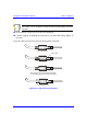
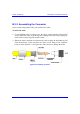
Connector advances in
this direction
Wire Slot
Figure B-3: Crimping tool
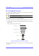
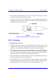
8. When finished, remove the connector from the right side of connector slot.
Note: The connector must be inserted into the crimper from the left hand side
only.
Should the connector jam in the terminating position, excessive force must not
be used: the spigot between the tool handles should be used to release the
ratchet mechanism.
The crimper handle will not allow release until a full termination cycle of the
connector has been completed.
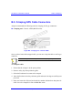
B.1.3. Inspecting the Crimped Connector
Each crimped connector is to be tested that it has been correctly crimped:
! Ensure that the wire extends beyond the front pin contact slot by a minimum of
0.5 mm
! Ensure that the two legs of the insulation crimp barrel are closed to secure the
insulation of the wire