
Install Guide Part 3

Installing the SPR Hardware Installation Guide
8-28 Airspan Networks Ltd. 02030311-05
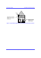
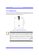
Note: You can connect the RSS LED adapter’s 15-pin male port directly to the
SPR’s 15-pin port, instead of using a cable.
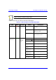
Table 8-5 describes the LEDs on the RSS LED adapter.
Table 8-5: LED description of the RSS LED adapter
LED Color Function Status Description
On
The SPR receives power from
the SDA
Off
No power is supplied to the
SPR by the SDA
Power Red
Power
Blinking
Data transmission is occurring
on the Ethernet LAN
LED 1 blinking RSS ≤ -94 dBm
LED 1 is on -93 dBm ≤ RSS ≤ -90 dBm
LEDs 1 and 2 are
on
-89 dBm ≤ RSS ≤ -86 dBm
LEDs 1, 2, and 3
are on
-85 dBm ≤ RSS ≤ -82 dBm
LEDs 1, 2, 3, and 4
are on
-81 dBm ≤ RSS ≤ -78 dBm
LEDs 1, 2, 3, 4,
and 5 are on
-77 dBm ≤ RSS ≤ -74 dBm
LEDs1, 2, 3, 4, 5,
and 6 are on
-73 dBm ≤ RSS ≤ -70 dBm
LEDs 1, 2, 3, 4, 5,
6 and 7 are on
-69 dBm ≤ RSS ≤ -66 dBm
RSS LEDs
(LEDs 0 to 7)
Green
Received
Signal
Strength
level
All LEDs are on RSS ≥ -65 dBm