
Install Guide Part 3

Hardware Installation Guide Installing the SPR
02030311-05 Airspan Networks Ltd. 8-19
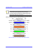
Notes:
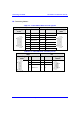
1) The wires are twisted together in pairs, for example, blue/white with blue,
and orange/white with orange. This prevents electrical interference between
the transmitter pins. For example, pin 3 (Tx+; orange / white) is paired and
twisted with pin 4 (Tx-; orange).
2) The SDA connector pinouts are the same for all SDA models (SDA-1, SDA-
4H, SDA-4S, SDA-4S/VL, SDA-4S/Vltag, SDA-4S/1H3L, and SDA-
4S/VL/1H3L).
Warning: To avoid electrical shock, before connecting the SPR to the SDA,
ensure that the SDA is not connected to the power supply.
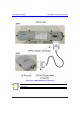
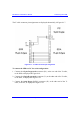
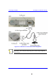
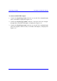
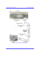
To connect the SPR to the SDA:
1. Attach the 15-pin D-type connector, at one end of the cable, to the SPR’s 15-pin
D-type port labeled DATA POWER SYNC, as displayed in Figure 8-15.
2. Attach the 15-pin D-type connector, at the other end of the cable, to the SDA’s
15-pin D-type port, as displayed in Figure 8-15.