
Install Guide Part 3

Hardware Installation Guide Summary of Connector Pinouts
02030311-05 Airspan Networks Ltd. D-9
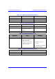
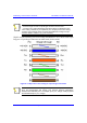
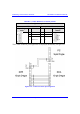
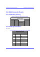
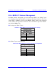
D.4.5. BSDU 100Base-T
Table D-11: BSDU 100Base-T LAN/WAN connector pinouts
Straight-through cable
8-pin RJ-45
Pin Name Description
1 Tx+ Transmit Data+
2 Tx- Transmit Data-
3 Rx+ Receive Data+
6 Rx- Receive Data-
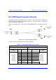
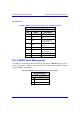
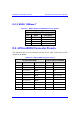
D.5. GPS-to-BSDU Connector Pinouts
The following table lists the connector pinouts for the cable connecting the GPS
antenna to the BSDU.
Table D-12: GPS-to-BSDU connector pinouts
12-pin female (GPS) 15-pin D-type male (BSDU)
Pin Pin name Cable color Pin Lead
1 POWER
Red
9
2 RX_DATA_1-
Blue
5 TD+ (after R5)
3 RX_DATA_1+
Black
6 TD-
4 TX_DATA_1-
Yellow
4 RD-
5 TX_DATA_1+
Black
3 RD+ (after R3)
6 RX_DATA_2-
Brown
x
7 RX_DATA_2+
Black
x
9 GND
Black
10
11 1PPS+
Green
8 1PPS-
12 1PPS-
Black
7 1PPS+ (After R7)