
User's Manual Part 2b

Hardware Installation Guide Installing the BSPS
02030311-05 Airspan Networks Ltd. 7-27
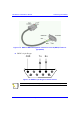
7.8.2. BSPS Equipment Supplementary Grounding
! Equipment housed in the BSPS cabinet must be supplementary grounded by
connecting a ground lead between each unit ground stud and the cabinet primary
ground stud.
! Cable specification is to be 2.5 mm
2
. Cable color-coding is to comply with local
regulations.
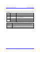
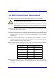
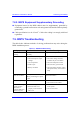
7.9. BSPS Troubleshooting
The table below indicates methods of solving problems that may arise during the
BSPS installation process.
Table 7-1: BSPS troubleshooting
Symptom Possible Cause Remedy
FAULT LED is
blinking
One or more rectifier modules
are faulty
Replace the faulty rectifier/s
FAULT LED is on
• Any breaker is left open
• Abnormal input or output
voltages
• Over temperature
• LVD is open
• Battery test failed
• Check all breakers
• Check line voltage and load,
rectifiers may be over-loaded
• Check the temperature sensor
• Check the line, general check
• Check the battery breaker, cables
and replace battery if none of this
helps
No backup time
when AC is absent
Battery is not connected
Battery is discharged or power
is low.
Check battery charge, connections
and circuit breaker
Load is not operating Load is not connected
• Check load cables.
• Check load circuit breaker.
No current sharing
among rectifiers
(more then 2
segments difference
between any two
• Load is too high.
• Extension rack is not
properly connected to the
main rack.
• Decrease the load or add rectifiers
to the system.
• Check connections.