
User's Manual Part 2b

Installing the BSDU Hardware Installation Guide
5-14 Airspan Networks Ltd. 02030311-05
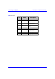
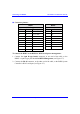
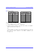
! Connector pinouts:
BSDU BSPS
9-Pin D-type RJ-45
Pin Name Description Pin Name
1 NC Not connected 1 NC
2 Rx Receive Data 2 NC
3 Tx Transmit Data 3 Rx
4 NC Not connected 4 NC
5 GND Ground 5 GND
6 NC Not connected 6 Tx
7 NC Not connected 7 NC
8 NC Not connected 8 NC
9 NC Not connected
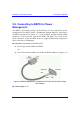
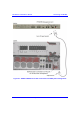
To connect the BSDU to the BSPS for BSPS serial power management:
1. Connect the 9-pin D-type female connector, at one end of the cable, to the
BSDU’s 9-pin D-type port labeled POWER Management (see Figure 5-7).
2. Connect the RJ-45 connector, at the other end of the cable, to the BSPS System
Controller’s RJ-45 serial port (see Figure 5-7).