
User's Manual Part 2b

Hardware Installation Guide Installing the BSPS
02030311-05 Airspan Networks Ltd. 7-7
7.1.3. BSPS Cabinet Cabling
This section defines the procedures to be adhered to when installing data cables in
the BSPS cabinet.
Note: A minimum separation of 200 mm should exist between power and data
cables.
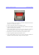
! Cable access apertures are located in the top surface of the cabinet. Separate
apertures are provided for power and data cables. All cabling entering and
exiting the BSPS cabinet shall be protected using flexible conduit and gland
systems suited to the cabinet. Power and data cables should exit from the BSPS
cabinet via separate apertures.
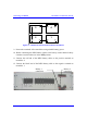
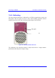
! Data cables are to be secured to cable guides provided on the left-hand side of
the cabinet when viewed from the rear. Cables are to be brought together to a
point on the cable guide from where they can be fanned out and fed to the Base
station Distribution Units (BSDU’s).
! Data cables terminating at the front of the BSDU’s should be fed through the
brush gland fitted adjacent to the units and secured to the cable management bar
using tie-wraps.
! When cabling the BSPS cabinet consideration should be given to future growth
and expansion. Allowances in cable forms should be made for the removal of
equipment for maintenance, i.e., BSDU’s, Power racks etc.
! Where cables are installed but not connected to equipment they should be tied
off in such a way as to prevent damage, allow for future growth and
maintenance. Pre-terminated cables should be treated with care and should not
be laid out in vulnerable areas where they may be susceptible to damage.
! Cable crossovers should be kept to a minimum to prevent system interference
and allow easy equipment removal.
! Ensure that the cables are dressed in such a fashion that they are not exposed to
hot exhaust air, sharp edges, doors etc.